- Topic ID: id_24368283
- Version: 2.0
- Date: Nov 7, 2019 8:53:50 PM
Power Distribution Unit Theory
This Cmodule covers NGPDU-6, 60, 61 and NGPDU-7, 70, 71.
This module contains the following sections:
-
Overview - Overview
-
NGPDU Physical Description - NGPDU Physical Description
-
NGPDU Service Overview - NGPDU Service Overview
-
NGPDU Electrical Specifications - NGPDU Electrical Specifications
-
NGPDU Drawings - NGPDU Drawings
-
NGPDU LEDs - NGPDU LEDs
-
NGPDU Control Board Switches and Fuses - NGPDU Control Board Switches and Fuses
1 Overview
The PDU provides a single location to connect input power for the entire CT system. Its function is to provide the following features to the System:
-
Provide compensation means for a wide range of input voltages via tap selection
-
Provide required system AC power from a single source
-
Provide High Voltage DC power for x-ray generation
-
Provide power for gantry axial rotation
-
Provide a means for emergency shutdown of all x-ray and drives power circuits
-
Provide system AC power circuit protection
-
Provide an interface for an external UPS connection
-
Meet the requirements of IEC601 for both radiated and conducted emissions
The PDU is designed to comply with United States Federal Regulations and the European Medical Device Directive. It bears the certification marks of a United States National Recognized Test Laboratory with Canadian deviation or a Canadian certified test house. Each unit is identified as being in compliance by being labeled with the official mark(s) of each respective agency.
While in the stand-by mode, the NGPDU does not generate sound levels in excess of 50dbA, when measured at a distance of one meter from the nearest cabinet surface, in any direction.
2 NGPDU Physical Description
2.1 Mechanical Enclosure
The enclosure has a front, rear and top access covers. The top cover is installed on the frame with a captive fastener in the middle of front edge. The front cover weighs less than 22 lbs (10 kg).
A single full-width Lexan safety shield is provided under the front cover. It extends ½” below the top front edge of the assembly to the bottom of all HVDC Supply components, including the PDU Control Board.
The rear cover is held in place by two captive fasteners. To maintain a good high frequency ground between internal subassemblies, all internal metal surfaces are solidly grounded to each other.
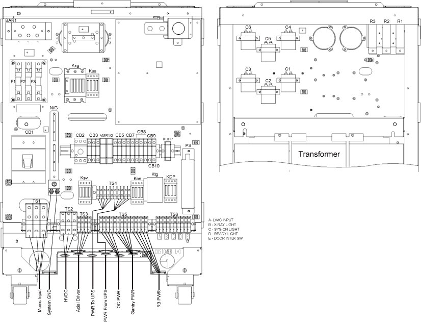
2.2 Component Locations
The main input transformer is located in the rear accessible chamber near the bottom of the cabinet, allowing enough room for cable access beneath. For ease of installation and serviceability the remaining components for the HVDC Supply and AC Power Distribution are located on the vertical dividing panel behind the front cover. Refer to Table 1 below, for general component information. Items numbers in table appear in circles of Figure 1.
Figure 1. Component/Physical Layout
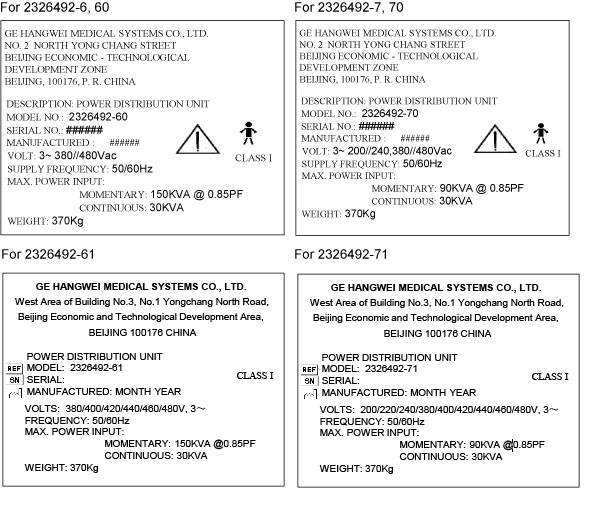
2.3 Product Labeling
The PDU has a rating plate permanently attached to the rear cover, near the top edge and approximately centered on the cabinet. It contains the following information:
Figure 2. Labeling
3 NGPDU Service Overview
3.1 Replacement Parts / Interchangeability
All replacement parts required for servicing the PDU are directly interchangeable without need of any re-adjustment. Circuit boards and sub-assemblies are given unique part numbers and revisions are completely backward compatible. Any changes to form, fit, or function which affect interchangeability shall require the assignment of a unique part number.
3.2 Service Tools
The PDU is designed so no special service tools are required. The assembly can be serviced with standard service tools.
4 NGPDU Electrical Specifications
4.1 Primary Input Power
The input power terminals accommodate #4 to #1/0 (fine strand) wire sizes. Ferrules are provided for the maximum wire capacity allowed. Input line fuses are used to protect the system. Dual element, time delay motor starting fuses are used.
4.2 Input Filtering
Low inductance, AC filter capacitors rated for mains connection are installed in a floating wye configuration on the three primary lines, on the load side of the fuses. Each capacitor is rated at 6.0 µF.
4.3 Input Transformer
The main input transformer is an indoor style, multiple winding, 3-phase isolation transformer. It has an open frame, varnish impregnated core & coil construction. It is suitable for continuous duty without requiring forced air-cooling. The insulation system used is UL, CSA, & IEC recognized for 180C (Class H) or better, and each transformer is labeled accordingly.
4.3.1 Magnetic Circuit
The magnetic circuit is designed for nominal 50/60 Hz operation (47 to 63 Hz limits). It accommodates a daily variation of ±10% input voltage, (i.e., 110% input voltage doesn’t cause excessive exciting current and core losses). Under worst case conditions, the transformer’s peak inrush current is less than 1000A when properly connected and energized at 380 V, 50 Hz.
4.3.2 Primary
All power for the CT System passes through the primary winding of the input transformer. It is protected by the primary input fuses described above.
The primary winding is designed for delta connection. Voltage selection taps are provided on each phase to accommodate 20 volt steps over the input voltage range of 380 to 480 V. All leads are brought out to a panel for external voltage selection. Leads are designated as follows:
(For NGPGU-71) The primary winding is designed for delta connection. Voltage selection taps are provided on each phase to accommodate 20 volt steps over the input voltage range of 200 to 240V and 380 to 480 V. All leads are brought out to a panel for external voltage selection. Leads are designated as follows:
Figure 3. PDU Tap Position for 480V Input Voltage
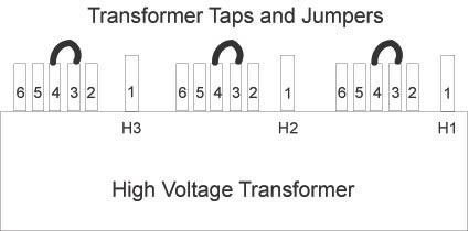
The gap in the winding between sections is located at the electrical middle of the winding. This feature allows the use of an alternate connection pattern for 200/220/240 volt input. In this configuration the PDU maximum momentary input rating is limited to 90kVa.
At shipment, the primary taps are set to the 480 volt connection.
4.3.3 Secondary #1 (designated as the “X” winding)
Secondary #1 is a 208Y/120V wye connected power winding. The phase leads are labeled X1, X2, and X3. The neutral, labeled X0, is isolated and brought out for external connection to ground.
Figure 4. Secondary “X” Winding Configuration

The full winding feeds general-purpose power to the CT system. The winding is protected at 50A per phase with a three-pole, 50A circuit breaker labeled CB3.
4.3.4 Secondary #2 (designated as the “Y” winding)
Transformer for Model 2326492-X:
Secondary #2 is a nominal 474Y/274V wye connected power winding. The phase leads are labeled Y1, Y2, and Y3. The neutral, labeled Y0, is isolated and brought out for external connection to ground.
Figure 5. Secondary “Y” Winding
The #2 secondary winding provides x-ray & drives power to the system. The full winding powers the HVDC supply. This is a six-pulse unregulated DC supply, which feeds the X-Ray source. As such, the output current is rich in the non-triplen odd harmonics. In particular, it contains ~35% 5th and ~15% 7th harmonic with additional higher harmonics being substantially lower magnitude.
The 440Y/254V taps feed an external Variable Speed AC Motor Drive. Assuming an 8% duty cycle, this drive produces an effective load current of 4.6A per phase. These taps are to be protected at 16A per phase with a three-pole, 16A circuit breaker, labeled CB2.
4.3.5 Shields
Full width electrostatic shields are provided between the primary and secondary windings. These are made from 0.005” copper or aluminum foil, with a minimum 0.5” insulated overlap. Each shield is grounded to the core and frame with green leads as short as practicable. (The lead position and attachment method minimizes shield impedance to high frequency noise signals.)
4.4 AC Power Distribution
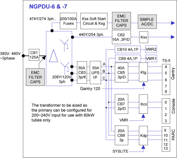
A general overview of the AC Power Distribution of the CT system is shown in the diagram below.
Figure 6. AC Power Distribution
4.5 General Purpose 120/208V AC Power Distribution
4.5.1 Full Winding Protection
The PDU Isolation Transformer, Secondary #1, supplies low voltage AC subsystem power. It is protected at 50A per phase with a three-pole, 50A circuit breaker. The full winding protection breaker is labeled CB3.
4.5.2 UPS Interface
A 10 position terminal strip, labeled TS4, is provided in the bulkhead for connection of an optional partial system UPS. This terminal block has compression type terminals approved for use with bare or stranded wire and is suitable for wire size 8AWG.
Terminals TS4-1 through TS4-5 provide output power connection to the optional UPS. Terminals TS4-6 through TS4-10 provide the power connections back to the NGPDU from the UPS. Connections are as follows:
Jumpers shall connect terminals 1 to 6, 2 to 7, and 3 to 8 with the PDU loads connected to the outputs of terminals 6, 7, & 8. These jumpers will be removed in the field whenever an optional UPS is used with the system.
4.5.3 Circuit Protection
AC power is distributed to the CT System via seven (7) separate branch circuits. These branches are protected by individual circuit breakers as follows:
4.5.4 AC Power Output Connections
The output connectors for AC power distribution to external subsystems shall be as follows:
4.6 High Voltage DC Power Supply
4.6.1 Electrical Requirements
The HVDC power supply is an unregulated, six pulse DC power source that feeds the high voltage subsystem used to generate x-rays. For model 2326492–X the output voltage of this supply ranges between a maximum of 740VDC (No Load) and a minimum of 480VDC (minimum sag at a maximum step load of 225ADC). For model 2326492-X the output voltage of this supply ranges between a maximum of 760VDC (No Load) and a minimum of 525VDC (minimum sag at a maximum step load of 100ADC).
4.6.2 Circuit Protection
The input to the HVDC Supply is the 3-phase, output from the transformer secondary #2 as previously described. Each phase of this winding is protected by semiconductor fuse, labeled F1, F2, F3. Fuse sizes are indicated below.
For model 2326492-6, 60, 61: F1, F2, F3 = 200 Amp, 690VAC
For model 2326492-7, 70, 71: F1, F2, F3 = 100 Amp, 690VAC
4.6.3 Construction / Description
The load side of the fuses is connected to a three-pole contactor, Kxg, having an AC1 rating of 100 Amps. The load side of the contactor is connected to the input of a 3 phase, full wave bridge rectifier / capacitor filter circuit. An auxiliary contactor, Kss, in series with a 20 ohms / phase resistive soft-start circuit is connected in parallel with the main contacts of Kxg.
-
EMC Filter Capacitors - C4, C5, C6
Low inductance, AC filter capacitors rated for mains connection are installed in a grounded wye configuration on the load side of Kxg. Each capacitor is rated 6.0 uF and has a minimum operating voltage rating of 330 VAC with a surge voltage rating of at least 2KV. If metal can style capacitors are used, their cans are solidly grounded to chassis metal and they are suitable for 330 VAC line to ground operation.
-
Bridge Rectifier - BR1
A 3-phase, full wave bridge rectifier rated 200 Amp, 1600V is used. The bridge rectifier is mounted to an aluminum heat sink, approximately 2°± X 6°± X 1/4°±. Aluminum Association Type 1100- F or equivalent aluminum is used. Thermal compound is used between the heat sink and rectifier and between the heat sink and chassis-mounting surface in accordance with the bridge manufacturer's specification.
-
HVDC Filter Capacitor(s)
The DC output of the bridge rectifier is filtered with two 4700uf, 450 volt electrolytic capacitors connected in series across the output terminals of the bridge. A discharge resistor network for each capacitor is included on the PDU control board.
4.6.4 Output Terminations - TS2
HVDC output leads from the capacitors terminate in a three position terminal block, labeled “TS2”. In addition to the cable ground connection, a cable clamp is provided at the NGPDU bulkhead, which is used for strain relief and 360. termination of the shield of the field installed cable.
4.7 Axial Drive Circuit
4.7.1 Electrical Requirements
The 440V taps of secondary #2 are used to power an external variable speed AC motor drive used for axial rotation of the gantry. The drive uses a conventional three-phase full wave bridge rectifier input circuit. This produces strong 5th & 7th harmonic currents typical of 6-pulse rectification. The maximum load under gantry acceleration conditions is 15A.
4.7.2 Circuit Protection
The circuit is protected at 15A per phase with a three-pole, 16A circuit breaker, labeled CB2.
4.7.3 Axial Drive Contactor
The CB2 circuit breaker feeds a three-pole contactor, labeled Ksv. The contactor’s 120VAC coil is controlled externally by the CT system. Auxiliary contacts on the contactor provide status feedback information to the system.
4.7.4 Output Terminations
Output leads from the Ksv contactor terminate in a four position terminal block, labeled TS3. In addition to the cable ground connection, a cable clamp is provided at the NGPDU bulkhead, which is used for strain relief and 360. termination of the shield of the field installed cable.
4.8 Control Signals
The PDU provides all power to the CT system. A PDU Control Board is located within the unit and provides for proper sequencing of the sub-system power, servo system, and x-ray backup contactor when commanded by the system. To facilitate control, the PDU Control Board contains a low voltage limited energy (LVLE) 24Vdc power supply, which provides the necessary communication power to the system. The output voltage of this supply is 24 VDC, ±3 volts for all conditions of line and load.
4.8.1 Subsystem Signal List
The following is a list of PDU Control Signals, that are accessible by means of a 25 position, female subminiature D type receptacle connector located in the output bulkhead. This connector is labeled J1.
4.8.2 Room Warning Light & Door Interlock Connections
A ten position terminal block, labeled TS6, is provided in the output bulkhead for connection of the customer room warning lights and door interlock. This terminal block has compression type terminals approved for use with bare or stranded wire and shall be suitable for a wire size range of 14 to 10AWG (2.25 to 5.5 mm2).
Terminals 1 through 8 are used for connection of external hospital room warning lights as described below. Terminals 9 & 10 are used for connection of a room door interlock switch in the system x-ray enable circuit.
-
EXTERNAL “XRAY ON” LIGHT - A normally open relay contact rated 125 VAC, 10 Amps is connected between Positions 3 & 4 of the terminal block.
-
EXTERNAL “SYSTEM ON” LIGHT (Currently this function is not yet available) - A normally open relay contact rated 125 VAC, 10 Amps is connected between Positions 5 & 6 of the terminal block.
-
EXTERNAL “GENERATOR READY” LIGHT - A normally open relay contact rated 125 VAC, 10 Amps is connected between Positions 7 & 8 of the terminal block.
-
Positions 2, 4, 6 and 8 of the terminal block are jumpered together. Series RC networks having a resistance of 470 ohms, a capacitance of 0.47 uF and a voltage rating of 250 VAC, are connected across terminal block positions 3 & 4, 5 & 6, and 7 & 8 on the Control Board.
-
The terminal block is labeled as follows:
In addition, the following information appears near the terminal block:
|

-
ROOM DOOR INTERLOCK - Positions 9 & 10 of the terminal block provide for a Room Door interlock in the X-Ray Exposure control of the system. Terminal 9 is to be connected to the EXP_INTLK signal (J1-17) and terminal 10 is to be connected to PDU_PGND on the PDU Control Board.
-
These terminals are clearly labeled “DOOR INTLK SW”.
-
At shipment from the factory, each NGPDU has a 14 AWG (2.25 mm2) jumper wire installed between terminals 9 & 10.
5 NGPDU Drawings
5.1 Gantry Power Control
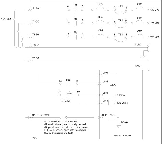
When the 120VAC ON signal is received at the GANTRY_PWR connection, given the auxiliary power switch is closed, relay coil KD2 is energized and its contacts close. This relay completes the circuit to the coil of Ktg, which in turn completes the 120VAC circuit to the gantry and table. See Figure 7. Gantry and table power is protected by CB5.
Table and gantry service outlet power is unaffected by 120VAC ON signal and can only be disabled by its associated circuit breaker CB4. Note that CB5 is slaves to master circuit breaker CB3. Table service outlet is limited to 10 amperes.
Figure 7. Gantry Power Control
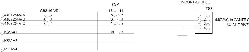
5.2 Axial Drive Power Control
Axial Drive Power is controlled by relay Ksv and is protected by circuit breaker CB2. When the PDU control board senses an e-stop condition, NGPDU is disconnected with Gantry_PWR_CLSD loop, which prevents activation of the relay Ksv.
Figure 8. Axial Drive Power Control
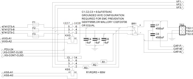
5.3 HVDC Supply Control
When the XG-CONT signal is received, the HVDC supply will produce output. When the coils KD4 is energized, the coil Kxg is energized. The contacts on Kxg close and supply power to the HVDC supply. This operation can be inhibited by the PDU control board “E-stop” circuit, through relay contacts Ktg. See Figure 9.
Figure 9. HVDC Supply Control
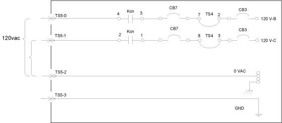
5.4 Console Power Control
120VAC Power for the console is derived from two legs of 208VAC. Console power is protected by circuit breaker CB7. CB7 is a slave to CB3.
Figure 10. Console Power Control
5.5 Room Light Control
Figure 11. Room Light Control
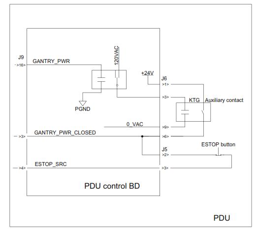
5.6 E-Stop Control
For the following discussion, see Figure 12.
-
Normal State
When the GANTRY_PWR signal is received, KTG contractor is closed, +24V DC output is given from PDU E-stop button (normally closed) to E-stop control loop in Gantry.
-
E-Stop
When an E-stop switch is activated, the connection between 24V and ESTP_SRC is opened, ESTP_SRC voltage dropped to 0V DC.
Figure 12. E-Stop Control
6 NGPDU LEDs
There are 17 LEDs on the PDU Control Board. See Figure 13.
Figure 13. LEDs on the PDU
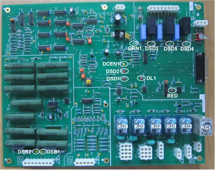
The ON / OFF status of these LEDs are explained in the below table:
7 NGPDU Control Board Switches and Fuses
The SW2-MNL_HVDC switch is set to the AUTO OFF position from the factory and must always remain in the AUTO OFF position.
-
No service procedure requires the use of this switch.
-
This switch should never be tampered with by Field personnel for any reason including troubleshooting NGPDU problems unless explicitly directed to do so by CT Engineering.