- Topic ID: id_16158082
- Version: 2.0
- Date: Dec 29, 2020 1:01:39 AM
Performix Plus tube theory with liquid bearing rotor management
1 Overview
New bearing technology allowing for longer life and higher gantry loads and bearing life is no longer tied to rotor on-time. Unlike ball-bearing anodes, the number of times that the liquid metal bearing comes to a complete stop (“landings”) should be minimized. Landings introduce wear in the bearing that will limit tube life. Bearing has friction, generates heat and needs oil cooling. The amount of heat generated is a function of bearing speed. Bearing rotation is unidirectional; reverse rotation causes damage. Landing the bearing (stopping it) causes contact and wear.
2 Rotor Management
Figure 1 illustrates an expected sequence of events for rotor management. When the tube is being operated in High Speed (HS), the Generator is driving the rotor, in pulse mode, between 138 and 149 Hz. When the tube is in Low Speed (LS), the rotor is being driven pseudo-continuously at 20 Hz (the drive pauses every 10 seconds for rotor speed measurement).
Figure 1. Performix Plus Rotor General Rule
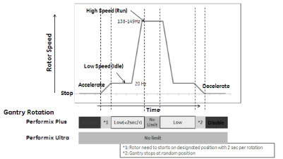
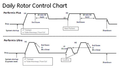
Figure 2 shows the relation between system functions and Performix Plus/Ultra rotor status.
Figure 2. system functions and Performix Plus/Ultra rotor status
When the scan starts in the following system functions and rotor is not rotating, system will start the rotor and accelerate to HS mode.
-
New Patient
-
Warm-up
-
Fastcal
-
Emergency patient
-
Service Tools
When the “confirm” pressed in the upper system functions during the rotor is in HS, system will keep rotor HS.
When the scan starts in the upper system functions and rotor is in LS, the system will accelerate the rotor from LS to HS.
The system will keep rotor speed in HS during the patient exam. (Rotor speed will be HS for the Stationary (Scout) and the Rotational (Axial) series.) If the rotor is in HS, system will decelerate the rotor to LS with passing 20 minutes after completing the Fastcal and Tube warm-up, clicking end exam, completing the SV tools.
When a system shutdown or restart is initiated, system will stop the rotor.
3 Rotor Start-up Method
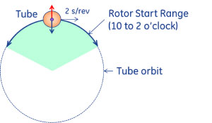
The gantry will start the rotor, in High Speed, when the tube is between 10 o’clock and 2 o’clock, with the gantry speed at 2 s/rev. This ensures that centrifugal forces cancel gravitational forces on the rotor, which minimizes wear during rotor start.
Figure 3. Rotor Start-up Method
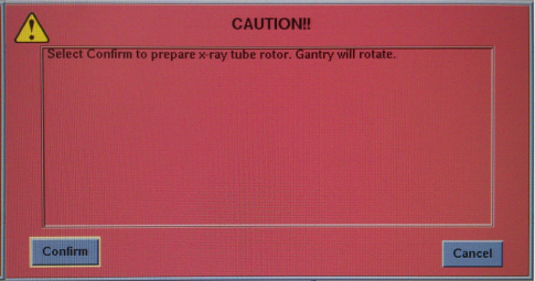
System will display the warning message to confirm the operator before to start-up rotor runs at high speed.
4 Rotor Stop Method
When a system shutdown or restart is initiated, system will stop the rotor.
If the rotor is rotating in HS, the system will brake the rotor to LS and let the rotor to coast to stop.
If the rotor is rotating in LS, the system will let the rotor to coast to stop.
The system will rotate the gantry in slower or equal to 2 s/rev. and stop the gantry at random position to stop the rotor.
System will display the warning message to confirm the operator before to move the gantry at random position.
Some service tools need to stop rotor to enter the diagnostic mode.
If Axial power is off, Rotor will stop without Gantry rotation.