- Topic ID: id_2025004
- Version: 4.0
- Date: Aug 10, 2021 9:58:34 PM
LOTO - Mechanical and Electrical - Table
Apply LOTO to the table
|

|
|
|
|
|
1 Electrical LOTO
The table electrical energy comes from the PDU through the gantry. Before opening the Table for service actions perform the following steps as required by the service procedure.
- Use the gantry keypad to fully retract the cradle and base to the HOME position.
- Use the gantry keypad to raise the table to maxim elevation.
- Remove the Bottom Rear and Bottom Front Collision Sensor covers to expose the bellows mounting screws.
Figure 1. Bottom Rear Collision Sensor
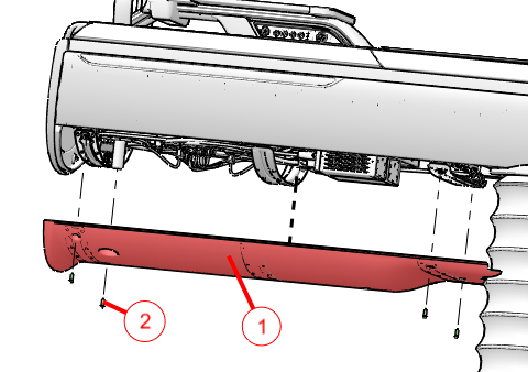
1 Rear Collision Cover 2 Four M5x16mm Hex Cap Screws Figure 2. Bottom Front Collision Sensor
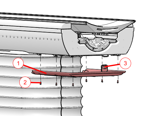
1 Front Collision Cover 2 Six M5x16mm Hex Cap Screws 3 Collision Tape Sensor Connector - Disconnect the front collision tape sensor harness and move the Service Shorting Plug from its storage location to the Service Position shown.note: The shorting plug must be installed in the Service position to allow table movement while in Service Mode.
Figure 3. Collision Sensor Shorting Plug
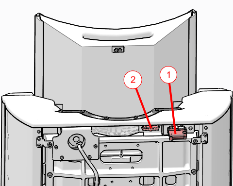
1 Shorting plug in Service Position 2 Storage position for shorting plug - Remove the Base Back Cover shown in figure for access to the RTCB Service panel within the electronics cage.
Figure 4. Base Back Cover Removal
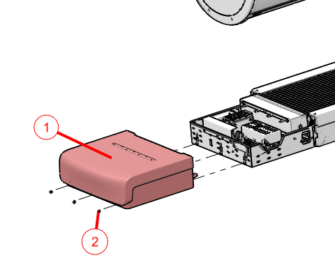
1 Base Back Cover 2 Three M5x12mm Hex Button Head Screws - Drop the upper bellows shown in the below figure to expose the LOTO clevis.
Figure 5. Top Bellows Upper Ring Removal
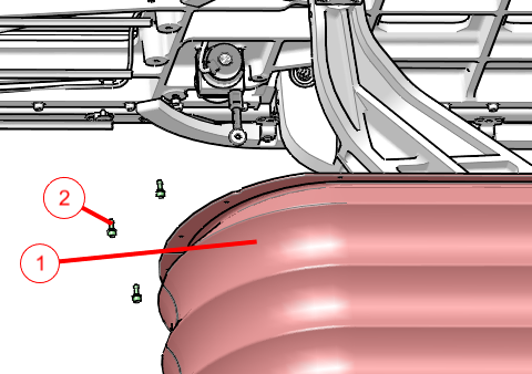
1 Bellows assembly with upper mounting ring shown 2 18 Captive Socket Head Screws note: Only 3 screws are shown in the figure for clarity and are shown non-captive. - Use the RTCB service panel to perform table LOTO.
- Press the AXIS_SEL button until the ELEV LED is ON.
Figure 6. RTCB Service Panel
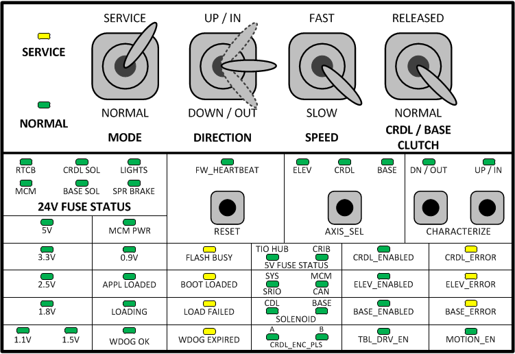
- With the SPEED switch set to SLOW, use the DIRECTION switch (UP or DOWN) to adjust table height until the hole in the LOTO clevis lines up with the outer locking hole.
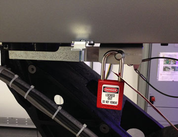
Figure 7. LOTO Locking Pin in Service Position
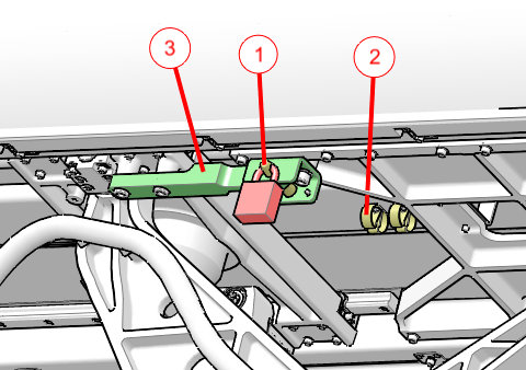
1 LOTO pin inserted into locking position, with lock attached. 2 LOTO pin storage location 3 LOTO clevis - Move LOTO pin from storage location and insert into aligned holes.
- Attach LOTO lock.
- Press the AXIS_SEL button until the ELEV LED is ON.
- Apply electrical LOTO according to Electrical LOTO - A1 Panel.
- Wait at least two minutes before verifying power is OFF at the table electronics cage. After two minutes all LEDs on the RTCB, MCM’s, and 160V power supply should be OFF.
2 Mechanical LOTO
The table is designed to move up and down and is driven by an electric motor screw drive to operate a scissor action table support. Failures within the drive could cause the table to move down without external commands. The table has a lock bar under the right side top rail, beneath the bellows, for use with a LOTO lock to prevent motion during service repair actions.
Figure 8. Table LOTO Lock Position