- Topic ID: id_16157884
- Version: 3.0
- Date: Apr 22, 2019 12:56:04 AM
GT1700V Theory
1 Overview
The GT1700V is a next generation table system used for BrightSpeed Velocity system. This Table is inherited from GT1700 and modified to support limited changes for the BrightSpeed Velocity Table subsystem. The intermediate support (IMS) is fixed in position by spacer blocks and the IMS drive components is removed. The fixed position IMS accommodate future Table mobile requirements and provide a cost savings versus GT1700.
The main features of the table system used on this CT system, compared with GT1700, are as follows:
-
IMS Removal
-
Adding new touch switch
-
Make cover rigidity higher
-
Firmware Change (Interference matrix, Cradle Auto-correct feature etc)
-
RIM IMS COVER introduction
-
Relocate elevation pot assembly
-
Modified foot switch assembly
-
GTCB3 Release (RoHS Compliance)
1.1 Table Control Firmware
The firmware that resides on the table itself (on GTCB) was designed so that it is common firmware between table types. During power up of the table, the GTCB firmware determines if the table is a GT2000, GT1700, NP Lite Table or GT1700V by checking Table Type Contactor on GTCN board.
1.2 Characterization
The GT1700V requires characterization for two axes, cradle and elevation.
Comparison of Characterization process between GT1700V and GT1700 :
-
Cradle: Same char process and char points as GT1700V.
-
Elevation: New
2 Block Diagram
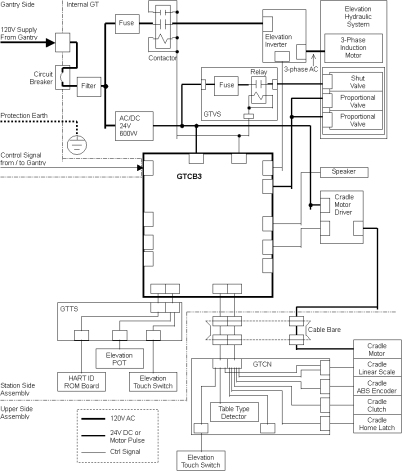
The following is the GT1700V Block diagram.
Figure 1. GT1700V Block Diagram
For a larger version of the illustration, click on the pdf icon below:
Figure 2. Table Block Diagram
5122080-10SCH_s1_r1.pdf3 Cradle Drive
3.1 Overview
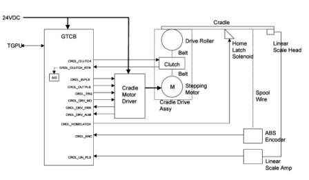
Control of this cradle drive system is provided by the GTCB3 (Global Table Control Board 3) and stepping motor driver. The GTCB3 generates the IN/OUT drive pulse and sends torque control signals to the stepping motor driver. The stepping motor driver drives the cradle stepping motor. The motor turns a drive roller at the front of the table on which the cradle rests via drive belts and clutch, thus causing the cradle to move.
Figure 3. Cradle Drive
3.2 Stepping Motor Driver
Stepping motor driver drives the stepping motor by the push-pull pulse from the GTCB3. The speed of driving depends on the frequency of the pulse. Stepping motor driver also controls the current to the stepping motor according to the command from the GTCB3 to control the torque. Stepping motor driver has 8 steps of the volume of the current to the stepping motor, depending on the level of the torque control signal from firmware.
3.3 Position Sensing
For cradle position control, there are two sensors; Multi-turn Absolute Encoder and Linear Scale Sensor. During power-up or reset sequence, the GTCB3 firmware collects the value of the Absolute Encoder to know the initial position of the cradle. Once the GTCB3 gets the initial position of the cradle, the Linear Scale Sensor is used for sensing the relative position of the cradle from the start position. It sends the data on RS485 serial interface. The Linear Scale sensor sends the Pi/4-shifted dual quadrature pulse each 0.01mm movement. And it has alarm output and external reset input.
3.4 Clutch
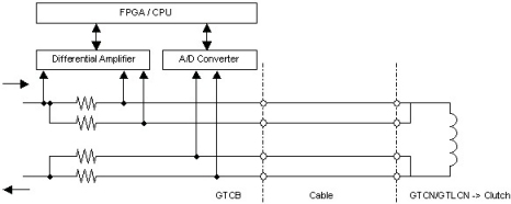
To avoid unexpected release of the clutch caused by cable failure or disconnection, the Cradle Clutch control line is duplicated, and the current is watched by A/D converter on the GTCB3.
Figure 4. Clutch Function
4 Elevation
4.1 Overview
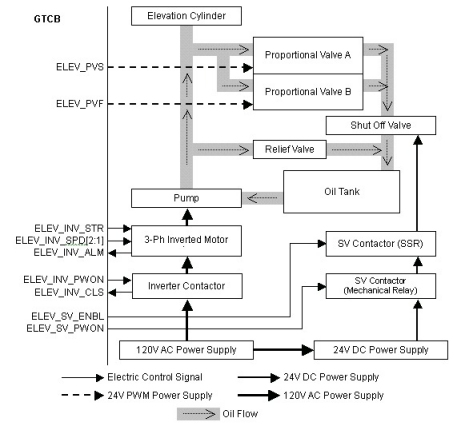
The Table has two modes of speed for Upward and two modes of speed for Downward. The Inverter makes the PWM signal and sends it to the Pump automatically to make a smooth ramp of speed according to the ELEV_SPD signal. The Pump is controlled by the Inverter, and puts oil into the Elevation Cylinder. The Relief Valve opens its own valve mechanically when the oil hydraulic pressure is higher than its threshold.
The Proportional Valves A and B, which have a role in removing oil from the Elevation Cylinder, controls oil flow volume by input voltage which is applied as a PWM signal with 24V amplitude. They are the same components, so that the speed of oil flow is twice of the single valve immediately after they are activated at the same time. The Shut-off valve is equipped to shut oil flow in case of oil leaking from the proportional valves.
The Inverter contactor is normally turned on. On the other hand, the SV (Shut-off Valve) Contactor controls each downward operation.
Figure 5. Elevation Function
4.2 Position Sensing
The GTCB3 measures elevation height by reading the digital-converted value of the voltage from the Elevation Potentiometer. The potentiometer is a 5K ohm resistor, and 4.8VDC is supplied. When the table is moving up or down, the A/D converter is sampled by the firmware. The value from the A/D converter represents the table’s position. When the specific position is ok, the firmware stops the control signal.
4.3 Touch Switches
There are several touch switches equipped on the Table to prevent pinching of a person or object. Six of them are the tape switches located around the TOP FRONT COVER. There is also one mechanical switch located at rear of the table.
Figure 6. Locations of Touch Switches
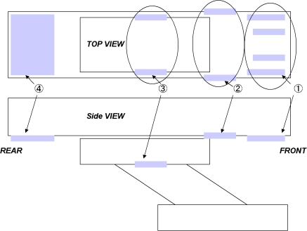
The Tape switches are connected through the internal 470-ohm resister. It can detect failure of the tape switch (open mode) or disconnection of the cable as well as detecting contact of the table with any object.
The Mechanical switches are connected through the internal 5.1k-ohm resister. It can detect failure of the tape switch (open mode) or disconnection of the cable as well as detecting contact of the table with any object.
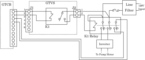
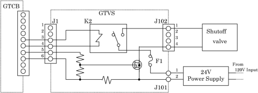
4.4 GTVS Board (5127381-2 or Later Inverter Assembly Only)
This board is attached to Inverter assembly in Global Table, and controls the relays and FET for elevation actuators by GTCB signals.
INVERTER RELAY CONTROL
Figure 7. Inverter Relay Control
SHUTOFF VALVE CONTROL
Figure 8. Shutoff Valve Control
5 Service Function
For Service and Engineering use, the GTCB3 rovides some switches as shown below.
Figure 9. Service Switches and relative LEDs
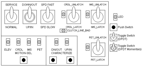
Figure 10. Service Switch Block Diagram
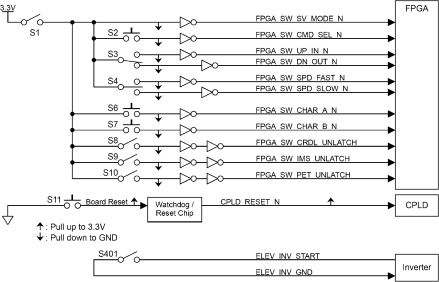
The following table shows the total switches of the GTCB3
The following table shows function of each switch or signal.
6 Fuses
The following table shows the list of fuses on the GTCB3.