- Topic ID: concept_r2v_rwr_w3b
- Version: 4.0
- Date: May 22, 2022 10:32:51 PM
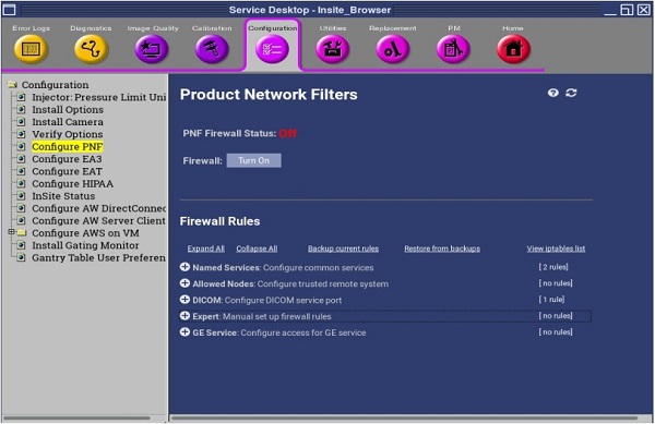
Configure Product Network Filters (18BW42.xx or Later)
1 Overview
Product Network Filters (PNF) is a software tool that allows a site Network Administrator to control traffic from the site's internal network to the Diagnostic Imaging System.
- Application software must be up.
- Click the Service icon to access the Common Service Desktop (CSD).
- Select the following:
- The Main PNF Screen is displayed.
Figure 1. Example for Configure PNF - CSD, Configuration Tab
 |
|
2 Firewall Setting
|
|
Figure 2. Main PNF Screen
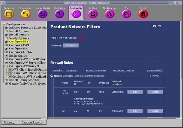
For 20BW15.25 or later, PNF is always reset to ON when system reboots. In order to turn the firewall ON or OFF, ClassM Hard Key needed.
- Click the Firewall On/Off button, turn Firewall On or Off.
- Click the Apply button on the pop-up window.
- The Firewall On/OFF buttons are common across all tabs in the PNF tool pages. These buttons can be clicked at any time and in any tab. The function of that button will be applied by the tool at the current state of all tabs.
3 Filter Setting Page
3.1 Named Services Tab
Figure 3. Filter Settings Page - Name Service Tab
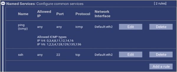
Figure 4. Filter Settings Page - Name Setting
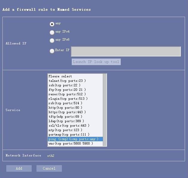
- Adding a Named Service.
- Click Add a rule.
- To add a network service, click the drop-down menu labeled Service Name for a list of standard Networking Services.
Standard Networking Services offered are:
- ftp
- http
- https
- ldap
- ntp
- ping (icmp)
- portmap
- rexec
- rlogin
- rsh
- ssh
- ssl / tls
- telnet
- tftp
- If desired, the Named Service may be restricted for use by a specific IP Address(es). Add IP Address(es) in the Enter IP field.
- Click Add button.
- Deleting a Named Service, select the object and click the Delete button.
3.2 Allowed Nodes Tab
Figure 5. Filter Settings Page - Allowed Nodes Tab
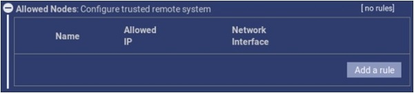
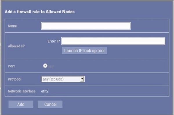
Figure 6. Filter Settings Page - Allowed Nodes Setting
- Adding an Allowed Node.
- Click Add a rule button to create a new Allowed Node.
- Enter the IP address in the Enter IP field.
- Click Add. This IP is now added to the list.
- Removing an Allowed Node, select the object and click the Delete button.
3.3 DICOM Setup
Figure 7. Filter Settings Page - DICOM Tab
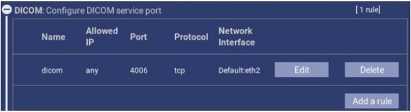
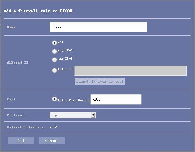
Figure 8. Filter Settings Page - DICOM Setting
- Adding a DICOM Port.
- Click Add a rule button to create a new DICOM Port.
- Enter the Port number in the Enter Port Number field.
- Click Add. This Port is now added to the list.
- Removing the DICOM Port, select the object port and click the Delete button.
3.4 Expert Tab
Figure 9. Filter Settings Page - Expert Tab
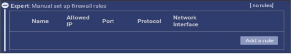
Figure 10. Filter Settings Page - Expert Setting
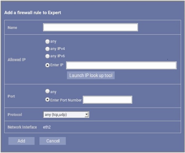
- Creating a Rule.
- To create a rule for the firewall, enter the application name in the Name field.
- Enter the IP Address/es in the Allowed IP field.
- Enter the Port in the Port field.
- Click on the Protocol drop-down menu for the rule to be applied (ex: all, tcp, udp).
- Once all fields have been populated, click Add button.
- Removing a rule, select the object rule and click the Delete button.
3.5 GE Service Tab
Figure 11. Filter Settings Page - GE Service Tab
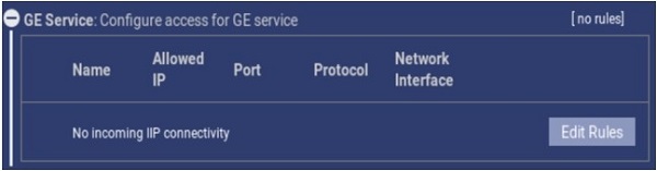
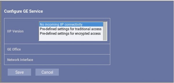
Figure 12. Filter Settings Page - GE Service Setting
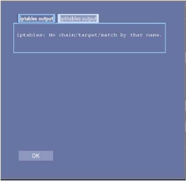
3.6 Iptables List
Figure 13. Iptables List
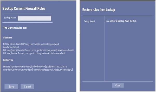
3.7 Backup/Restore Page
Figure 14. Backup/Restore Page
3.8 Troubleshooting
Troubleshooting the firewall can be done by turning the Firewall On and Off.
|
|
4 Finalization
When all the necessary changes/settings have been made, perform the following step:
- Perform a Save System State to capture PNF Configuration settings and rules in System State backup. Perform the System State Save Restore instructions from the procedure list.