- Topic ID: id_15460276
- Version: 3.0
- Date: Jun 15, 2020 11:01:02 PM
VeRB 1 or 2 Replacement with DIG-VeRB Common Computer
Prerequisites
Overview
This procedure describes steps necessary to replace the VeRB 1 or 2 with a DIG-VeRB Common Computer. The DIG-VeRB Common Computer does not contain the DIP and SAS cards which are only used in the DIG computer.
DO NOT REMOVE THE GPU FROM THE COMMON COMPUTER FRU
Definitions:
VeRB1 = Volume Reconstruction Box, the 1 means it has the Nvidia GPU
VeRB2 = Volume Reconstruction Box, the 2 means it has the AMD / ATI GPU
SAS = Serial Attached SCSI
DIP = DAS Interface Processor, either VDIP or HDIP
GPU = Graphics Processing Unit
BMC = Baseboard Management Controller (Hardware on the Mother board)
RMM = Remote Management Module ( Adapter Card )
IPMI = Intelligent Platform Management Interface ( BMC is IPMI compatible )
Ipmitool = Utility for controlling IPMI enabled devices
SNMP = Simple Network Management Protocol
PXE Boot = Preboot eXecution Environment (pronounced pixie) boots/retrieves OS & Application software over a network.
IP Addressing:
172.16.0.2 darc = DIG
172.16.0.5 verb = VeRB
172.16.0.3 darcrmm = DIG rmm
172.16.0.4 verbrmm = VeRB rmm
172.16.0.6 darcarray = darcarray
172.16.0.7 darcarray2 = darcarray2
172.16.0.10 darcbmc = darcbmc
172.16.0.11 verbbmc = verbbmc
1 Power-Off (Shut Down) the Console
Procedure
- Select one of the following methods to power off the Operator
Console:
-
Open a Unix Shell using the Toolchest.
-
Type: {ctuser@hostname} halt. Press Enter.
The Operator Console monitor will display a ‘System Halted’ message when it is acceptable to power off the Operator Console.
-
- Power OFF the Operator Console at the front panel switch. Perform prescribed Lockout/Tagout procedure. For added protection, disconnect the Twist-N-Lock Main Power Cable from rear of console.
2 Remove VeRB Computer
Procedure
- Remove the front and rear Operator Console covers per prescribed cover removal procedure.
- Remove the two network cables at the rear of the VeRB Computer
chassis being replaced. See Illustration below to identify the network
cables Verb ETH and RMM ETH.note:
Verify that all cables are labeled and clearly marked. If necessary, add a label for clarity.
- Remove the power cord at the rear of the VeRB Computer chassis.
- Remove the four (4) 5mm socket cap mounting screws and washers from the front of the VeRB Computer chassis, holding the chassis to the Operator Console rack.
- Slide the VeRB Computer chassis forward (out the front of console) and set aside.
- Remove two blank plates from the rear of the efective VeRB, to be used on the replacement VeRB.
3 Install Replacement VeRB Computer
Procedure
- Install two blank plates removed in the earlier step, to ensure proper airflow.
- Slide the replacement DIG-VeRB Common Computer into the Operator Console from the front.
- Replace the four (4) 5mm socket cap mounting screws and washers.
- Mount the power cord to the rear of the VeRB Computer chassis and verify that its power supply switch is turned to the ON position.
- Replace the rear network cable Verb ETH and RMM ETH.
Figure 1. VeRB Cable Connections & Destination
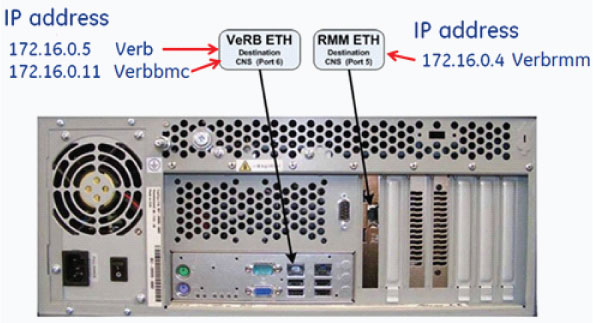 note:
note:For cabling details, refer to the appropriate interconnect located in the System Diagrams folder of this service methods publication.
4 Disconnect Power Cable from the DIG Computer
Procedure
- Disconnect power cable from the DIG computer.note:
The DIG-VeRB common computer is shipped configured as a DIG. Failure to disconnect the two network cables will cause network problems due to the IP addressing. The DIG-VeRB Common computer arrives configured as a DIG.
5 Power-On the Operator Console
Procedure
- Reconnect the Twist-N-Lock Main Power Cable from rear of console and remove Lockout Tagout protection applied earlier.
- Power ON the Operator Console at the console’s front panel switch.
- Cancel Application Startup when the CT Software Auto-start pop-up window appears.
Note: Do not allow Applications to start. During boot-up If you miss the 5 seconds to stop application type the following:
slay -f startMon
6 Verbrmm dhcpd setup
Enter the following commands:
Procedure
- Open a shell window, login as root su -
- Enter root password
-
sed -i '/subnet/a range 172.16.0.4;' /etc/dhcpd.conf
note:
Run step #4 command line once. If the command is entered more than once it will cause a problem. The /etc/dhcpd.conf file should only have one “range 172.16.0.4;” line inside the file. Every time step #4 is entered a duplicate Line will be entered. Running reconfig will correct the multiple entry issue in the dhcpd.conf file.
Note: ‘ = single quote
Note: -i = lower case letter i
Note: 172.16.0.4 verbrmm
- Service dhcpd restart
Example of Good Output:
Shutting down dhcpd: [OK]
Starting dhcpd: [OK]
- Ping verbrmm , the verbrmm should start responding
after 60 seconds.
Note: Press the verb power button maybe required to ping the verbrmm.
7 IPMI IP Address/Channel SETUP from a DIG to a VeRB
Procedure
- Open a shell window , login as root
- Type ipmitool –H verbbmc –P “”
lan print 1
Note: “” = two double quotes no spaces between them
Note: print 1 = print “the number one”
- If the output displays the following, Skip to Set RMM SNMP Settings
IP Address Source = Static Address
IP Address = 172.16.0.11
Note: 172.16.0.11 address is the verbbmc.
- Continue to Step 5. This message “Channel 1 is not a LAN channel” is normal.
- Type ipmitool –H darcbmc –P “”
lan print 1
Note: This command will print the darcbmc IP address, Write down the ip address for reference.
Caution slow down, the next command is very important enter it correctly.
- Type ipmitool –H darcbmc –P “”
lan set 1 ipaddr 172.16.0.11
The following messages are normal:
Example:
ipmitool -H darcbmc -P '' lan set 1 ipaddr 172.16.0.11
Setting LAN IP Address to 172.16.0.11 (write down the displayed IP address)
Set LAN Parameter failed
Set LAN Parameter failed
Set LAN Parameter failed
Close Session command failed
Note: “” = two double quotes no spaces between them
Note: print 1 = print “the number one”
Note: 172.16.0.11 = verbbmc
- Write down the IP address displayed/reported on the screen it should be 172.16.0.11 but if you miss type you will need the displayed IP address to recover.
- Type ipmitool –H verbbmc –P “”
lan print 1
Note: “” = two double quotes no spaces between them
Note: print 1 = print “the number one”
- Verify the screen output displays the IP Address Source as ‘static Address’, and the IP Address as ‘172.16.0.11’. (172.16.0.11 address is the verbbmc )
8 Set RMM SNMP Settings
Note: Caution – Do not to change any setting which is not documented. To access the RMM, open a Terminal Window, and log on as root:
Procedure
- Type: {ctuser@hostname} su-
- Type the root password
- Type: {root@hostname} mozilla verbrmm
Note: The Mozilla (Fedora) WEB Browser will appear.
Note: The WEB Browser will update and display the Login page for the VeRB (2) RMM.
- Username: Type: admin and press TAB
- Password Type: password and press ENTER
Note: If the RMM logon screen does not appear, try pinging the DIG and/or VeRB Computers. Try reconfig again. In Terminal Window, Type: ping verbrmm (172.16.0.4) or ping darcrmm (174.16.0.3)
- If the computers fail to respond to the ping command, check Network Switch and Cables. See DIG/VeRB Troubleshooting in the Troubleshooting Chapter in the Service Manual.
- Click Device Settings in RMM Navigation Menu on left side of browser
- Click SNMP Settings in RMM Navigation Menu on left side of browser
- Confirm following SNMP Settings are selected:
- Enable SNMP Agent
- Read Community is set to public
- Write Community is set to private
- Set System Location to either, GEHCVERB (GOC6) or GEHCVERB2 (GOC6.5)
Note: GEHCVERB or GEHCVERB2 Depends on Computer type and GPU card installed.
GEHCVERB = VeRB-1 = DIG/VRB-1 5255299-100 = Nvidia GPU
GEHCVERB2 = VeRB-2 = DIG/VRB-2 5255299-101 = AMD ATI GPU
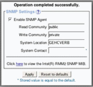
- Click Apply
-
Operation completed Successfully message
is displayed
Note: DO NOT Click Reset to defaults
- Close the Mozilla window.
- Type Halt the console
- Power off the console.
9 Reconnect Power Cable to the DIG Computer
Note: The power to the DIG was disconnected at Disconnect Power Cable from the DIG Computer
Procedure
- Reconnect power cable to the DIG computer previously removed.
- Power on the console
- Verify Verb and DIG power led is on, during boot up.
- Cancel Application Startup when the CT Software Auto-start pop-up window appears.
Note: Do not allow Applications to start. During boot-up If you miss the 5 seconds to stop application type the following:
slay -f startMon
- Verify Verb power is on if not press the Power-on button on the front of the Verb
10 Reconfig With Verb and DIG powered up
Procedure
- Run reconfig
- Open a Terminal window and log on as Root.
- Type: reconfig
- Select: Config
Note: No changes are required in the System, Preferences, Hardware, Network settings. The Accept button needs to be executed in order for the automated scripts to run. During the reconfiguration process the DHCP Server running on the Host Computer is reconfigured to support the new DIG Computer Ethernet MAC addresses
Note: Until the System Configuration procedure is performed, the Linux OS bootup text will display an error message when the DIG computer attempts to mount its NFS on the Host Computer. Ignore the error message.
Note: This could take up to 10 minutes waiting for the darc to boot up, please be patient
- Verify in the hardware setting Number of VeRBs = 1
- Select: Accept
- Do you wish to reboot Now ? YES Reboot for change to take effect –minutes
- Open a Unix Shell
Note: applications do not Autostart after a reconfig
- Type: st to bring application up
11 Finalization
Procedure
- Perform a complete shutdown of the Operator Console and restart the system.
- Confirm VeRB or DIG communication
- In Terminal Window, Type: ping verb and ping darc , reboot could take up to 10 minutes
- In Terminal Window, Type: ping verbrmm and ping darcrmm
- If these computers fail to respond to the ping command, check Network Switch and Cables. Otherwise suspect a failed computer. See DIG/VeRB Troubleshooting in the Troubleshooting Chapter in the Service Manual
- Run a patient scan to confirm proper system operation.
Select Image Quality tab -> QA Phantom ImgSer Or
Select Manufacturing tab -> Service System Scanning Test-> lower all ma settings to 40 ma
- Reinstall Console Front and Rear Covers.