- Topic ID: id_15460604
- Version: 2.0
- Date: Nov 8, 2018 1:37:44 AM
Tube Oil Cooling System Air Removal
Prerequisites
Overview
This document provides the necessary steps to remove air from the Tube Oil Cooling System.
The Tube Oil Cooling System is a closed system with the Heat Exchanger, Tube Oil Pump, and X-Ray Tube as its main components. In the event that air is introduced into the system, unusual Image Artifacts and/or tube over temperature issues can occur.
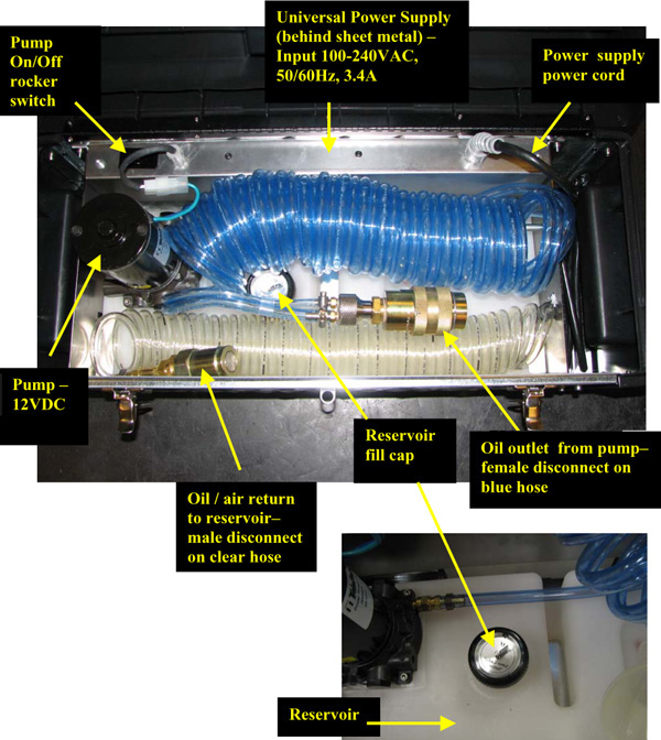
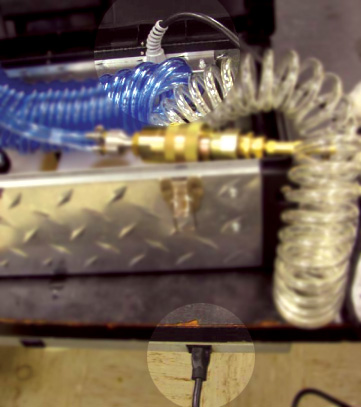
Figure 1. Tube Coolant Air Removal Kit
1 Apparatus Preparation
Procedure
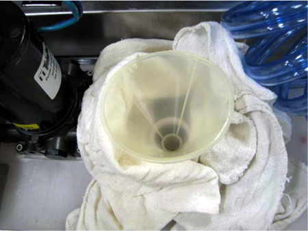
- Remove reservoir cap, position funnel into tank and place dry
wipes around funnel to capture any spilled oil (See Figure 2).
Figure 2. Funnel and Dry Wipes
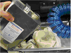
- Fill reservoir with approximately 1 US gallon of transformer
oil (See Figure 3).note:
At a minimum, make sure reservoir is 1/2 full prior to starting air removal procedure.
note:Reservoir’s volume is approximately 5 liters (1.3 gallons).
Figure 3. Fill Reservoir with Transformer Oil
2 Apparatus Air Purge
Procedure
- notice
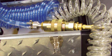
- Connect together apparatus female and male quick disconnects
(See Figure 4).
Figure 4. Connect Female and Male Disconnects
- Plug in apparatus power supply (See Figure 5).note:
Power supply is set up for 115V operation. However, it is a universal power supply and will work internationally with correct interface adapter.
Figure 5. Plug In Power Supply
- Turn on apparatus pump power switch.note:
Oil will flow through large blue hose into clear hose. Some incidental back flow through small blue hose is expected as well.
- When large blue hose is free of air (~ 30 seconds), turn off apparatus pump power switch and uncouple quick disconnects.
- Ensure apparatus reservoir is at least 1/2 full. If filling is required, see steps in Section 4.1.
 |
3 Preliminary Setup
Procedure
- Move table to home position.
- Remove gantry right side cover.
- Turn off HVDC ENABLE, AXIAL DRIVE ENABLE and 120 VAC ENABLE switches on Service Switch panel.
- Remove scan window, gantry left side cover, gantry top covers,
and gantry front cover.note:
Gantry front-cover control panels and display functionality are required during this procedure.
- Rotate gantry so that tube is between 1 o'clock and 2 o'clock positions.
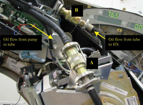
- Remove tube oil pump to tube quick disconnect safety mechanism bolts with a 5mm hex bit socket drive and uncouple quick disconnects (See Item A in Figure 6.).
- Remove tube heat exchanger to tube quick-disconnect safety mechanism
bolts with a 5mm hex bit socket drive and uncouple quick disconnects
(See Item B in Figure 6.).
Figure 6. Quick Disconnect Safety Mechanisms
4 Tube Air Removal
Procedure
- Unplug J52 pump power connection, disabling gantry oil pump.
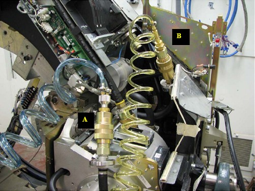
- Connect apparatus female quick disconnect to tube male quick disconnect (See Item A in Figure 7).
- Connect apparatus male quick disconnect to tube female quick
disconnect (See Item B in Figure 7).
Figure 7. Apparatus-to-Tube Quick Disconnects
- Turn on 120 VAC ENABLE switch on Service Switch.
- Press ESTOP RESET on Service Switch panel and wait until scan hardware is reset.
- Tilt gantry forward to +30 degrees so that top of gantry is tilted towards table.
- Turn on apparatus pump power switch.
- notice
- notice
- Slowly rotate tube to 3 o'clock position. Hold for 1-2 minutes,
raising return line periodically.
- Slowly rotate tube clockwise from 3 o'clock position to 6 o'clock position to allow air to rise to back of the tube. Hold for 1-2 minutes, raising return line periodically.
- Slowly rotate tube clockwise from 6 o'clock position to 9 o'clock position. Hold for 1-2 minutes, raising return line periodically.
- Slowly rotate tube counter-clockwise from 9 o'clock position to 6 o'clock position. Hold for 1-2 minutes, raising return line periodically.
- Slowly rotate tube counter-clockwise from 6 o'clock position to 3 o'clock position. Hold for 1-2 minutes, raising return line periodically.
- Slowly rotate tube counter-clockwise from 3 o'clock position to 12 o'clock position. Hold for 1-2 minutes, raising return line periodically.
- Slowly rotate tube counter-clockwise from 12 o'clock position to 9 o'clock position. Hold for 1-2 minutes, raising return line periodically.
- Slowly rotate tube counter-clockwise from 9 o'clock position to 6 o'clock position. Hold for 1-2 minutes, raising return line periodically.
- Slowly rotate tube clockwise from 6 o'clock position to 9 o'clock position. Hold for 1-2 minutes, raising return line periodically.
- Slowly rotate tube clockwise from 9 o'clock position to 12 o'clock position. Hold for 1-2 minutes, raising return line periodically.
- Slowly rotate tube clockwise from 12 o'clock position to 3 o'clock position. Hold for 1-2 minutes, raising return line periodically.
- Slowly rotate tube clockwise the tube from 3 o'clock position to 6 o'clock position. Hold for 1-2 minutes and raising the return line periodically.
- Repeat steps 10 – 21 a minimum of 2 more times until air is no longer being visibly removed.
- Turn off apparatus pump power switch.
- Turn off 120 VAC ENABLE switch on Service Switch.
- Uncouple apparatus female quick disconnect to tube male quick disconnect (See Item A in Figure 7).
- Uncouple apparatus male quick disconnect to tube female quick disconnect (See Item B in Figure 7).
- Turn on 120 VAC ENABLE switch on Service Switch.
- Press ESTOP RESET on Service Switch panel and wait until scan hardware is reset.
|
|
5 Pump and Heat Exchanger Air Removal
Procedure
- Tilt gantry back to 0 degrees.
- Turn off 120 VAC ENABLE switch on Service Switch.
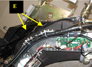
- Cut Ty-wraps holding pump hose in heat exchanger channel (See
Item E in Figure 8).
Figure 8. Ty-wrap Locations
- notice
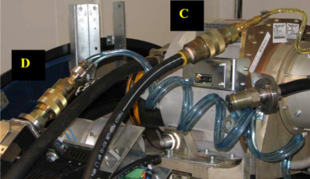
- Connect apparatus male quick disconnect to tube oil pump female quick disconnect (See Item C in Figure 9).
- Connect apparatus female quick disconnect to heat exchanger
male quick disconnect (See Item D in Figure 9).
Figure 9. Tube Oil Pump-to-Tube Heat Exchanger Quick Disconnects
- Turn on 120 VAC ENABLE switch on Service Switch.
- Press ESTOP RESET on Service Switch panel and wait until scan hardware is reset.
- Ensure apparatus reservoir is at least 1/2 full. If filling is required, see steps in Section 4.1.
- Perform Section 4.4, Steps 7 - 22.
- Uncouple apparatus male quick disconnect from tube oil pump female quick disconnect.
- Uncouple apparatus female quick disconnect from heat exchanger male quick disconnect.
- Remove apparatus from system and connect system components to each other.
- Plug J52 pump power connection.
- Turn on 120 VAC ENABLE switch on Service
Switch for 30 seconds, then turn off. note:
Remaining air is moved to heat exchanger.
- notice
- Unplug J52 pump power connection.
|
|
6 System Air Removal
Procedure
- Uncouple quick disconnects between tube oil pump and tube.
- Connect apparatus male quick disconnect to tube oil pump female quick disconnect.
- Connect apparatus female quick disconnect to tube male quick disconnect.
- Turn on 120 VAC ENABLE switch on Service Switch.
- Press ESTOP RESET on Service Switch panel and wait until scan hardware is reset.
- Tilt gantry forward to +30 degrees so that top of gantry is tilted towards table.
- Perform Section 4.4, Steps 7 - 21.
- Tilt gantry backward to -30 degrees so that top of gantry is tilted away from table.
- Perform Section 4.4, Steps 7 - 21.
- Tilt gantry forward to 0 degrees.
- Perform Section 4.4, Steps 7 - 22.
- Uncouple apparatus male quick disconnect from tube oil pump female quick disconnect.
- Uncouple apparatus female quick disconnect from tube male quick disconnect.
- Connect tube oil pump female quick disconnect to tube male quick disconnect.
- Plug J52 pump power connection.
7 Tube Heat Exchanger Compensation and Flow Rate Measurement
8 Finalization
Procedure
- Restore tube oil pump to tube quick disconnect safety mechanism
and torque M6 bolts with a 5mm hex bit torque drive to the following
values.note:
If safety mechanism rotates in relation to quick disconnect, tighten slowly until it stops rotating.
note:Do not over-torque M6 bolts. Doing so can cause quick disconnect to leak.
- Restore tube heat exchanger to tube quick disconnect safety
mechanism and torque M6 bolts with a 5mm hex bit torque drive to the
following values.note:
If safety mechanism rotates in relation to quick-disconnect, tighten slowly until it stops rotating.
note:Do not over-torque M6 bolts. Doing so can cause quick disconnect to leak.
- Ty-wrap hoses to tube heat exchanger.
- If another Service Procedure required procedure execution, perform
the following steps.
- Turn on 120 VAC ENABLE, AXIAL DRIVE ENABLE and HVDC ENABLE switches on Service Switch panel.
- Press ESTOP RESET on Service Switch panel and wait until scan hardware is reset.
- Return to associated Service Procedure.
- If procedure execution was not due to another Service Procedure,
perform the following steps.
- Install gantry front cover, gantry top covers, gantry left side cover, and scan window.
- Turn on 120 VAC ENABLE, AXIAL DRIVE ENABLE and HVDC ENABLE switches on Service Switch panel.
- Press ESTOP RESET on Service Switch panel and wait until scan hardware is reset.
- Install gantry right-side cover.