- Topic ID: id_15460483
- Version: 2.0
- Date: Nov 8, 2018 1:38:33 AM
TGPU Replacement
Prerequisites
Overview
This procedure defines the steps necessary to replace the TGPU board.
1 Removing The TGPU
Procedure
- Remove the gantry right side cover.
- notice
- Turn off all three (3) switches (Axial Drive, HVDC, and 120VAC) on the Service Switch Panel.
- Perform all required LOTO activities.note:
Front and rear access is required for this procedure.
- Remove gantry left side cover. If further access is required,
remove top and rear covers.
Refer to
- Remove the 8 thumbscrews in the TGPU cover, then remove the cover.
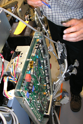
- Disconnect all cabling into the TGPU.note:
If the cables are not labeled, label them as they are removed.
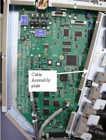
- Remove the cabling assembly plate.
Figure 1. TGPU
- Remove the eight (8) screws attaching the TGPU board.
- Remove the defective TGPU.
 |
2 Install TGPU
Procedure
- Put the new TGPU board in place.
- Secure the board by replacing the eight (8) screws (Figure 2.)
Figure 2. The TGPU Board Secured
- Install the cable assembly plate.
- Carefully install all of the removed cables, making sure that no pins are bent during engagement.
- Remove LOTO, and power up everything except the gantry.
- Before powering ON the 120 VAC gantry power, open a shell (terminal)
window on the console and type the following
cd /usr/g/fw ENTER
touch tgpFtp ENTER
note:These commands must be performed to assure that the FLASH download procedure successfully downloads the TGPU firmware from the OC, regardless of the status of the TGPU programming.
- Turn ON all three (3) switches (Axial Drive, HVDC, and 120VAC) on the Service Switch Panel and press the E-stop reset.
- Execute Flash download query and update. Refer to the Flash download procedure if necessary.
- Perform the power supply adjustment procedure in the Finalization
section of the TGPU Power Supply Replacement.note:
You will have to remove the M6 top and bottom mount screws holding the power supply in place using a 5 mm hex wrench as noted at the beginning of the power supply replacement procedure to have access to the adjustment screws.
- Turn off the Axial Drive, HVDC and 120 VAC service switches.
- Replace the TGPU cover.
- Replace gantry covers except for the right side cover that allows access to Service Switch Panel.
- Turn on the 120 VAC, HVDC and Axial Drive service switches.
- Replace gantry right side access cover.
3 Finalization
Procedure
- Perform the System Scanning Test from the Functional Checks folder.