- Topic ID: id_15460472
- Version: 2.0
- Date: Nov 8, 2018 1:38:33 AM
Stationary 48 Volt Power Supply Replacement
Prerequisites
Overview
This procedure defines the steps to replace the 48V Power supply on the stationary side of the gantry.
Procedure
 warning
- Remove gantry right side cover.note:
Replacement should be done from the front or back of the gantry.
Refer to
- notice
- Turn OFF the three (3) main power switches (HVDC, 120VAC, and Axial Drive) on the Service Switch Panel (SSP).
- Perform all required LOTO procedures before beginning this procedure.
- Remove the gantry left side cover. If more access is needed due to gantry position in room, remove gantry top and rear covers.
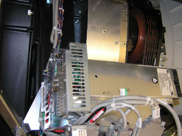
- The stationary 48Vdc supply is located on the gantry right side
above the TGPU. See Figure 1.
Figure 1. 48V Power Supply
 note:
note:There are different versions of the power supply, all attach to the same mounting points.
- There are four (4) hex head screws holding the supply on the mounting plate that will need to be removed.
- Rotate the power supply 90 degrees to gain access to the rear power safety shield and remove.
- Remove the AC and DC power connections.
- Reconnect all power leads to new supply power and mount the supply with the 4 screws.
- Install safety shield and all removed hardware and securely tighten
 |
Finalization
- Remove the Lockout/Tagout, and power up the console.
- Install all removed gantry covers. Be sure to reconnect all top cover fan connections. Check that no cables are left in the rotating path. Return dollies to storage areas.
- Turn on the 120 VAC, HVDC and Axial Drive service switches from the service switch panel.
- Make sure the top cover fans power on during gantry power up.
- Make sure the fan for the gantry heater/blower assembly is operating.
- Verify no gantry fan or heater/blower related error messages are shown in the system error log after gantry power up.