- Topic ID: id_15460629
- Version: 3.0
- Date: Jun 15, 2020 10:52:05 PM
Start Electrician on PDU Hookup
Prerequisites
1 Position the Power Distribution Unit
Procedure
- Roll the PDU into position on its permanently mounted casters.
Leave at least 15.5 cm (6 in.) between the PDU and back wall to allow
cooling air to circulate.
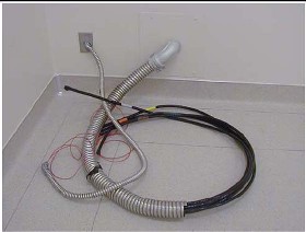
- Run the main input power conductors and ground though flexible
metal conduit (attached between the PDU chassis and room duct-work)
so you can move the PDU away from the wall during service.
Figure 1. Flexible Conduit for PDU Power
- Locate the hole cover plate in Box 1 and attach the flexible metal conduit to the PDU.
- If present, remove the TS1 panel front cover.
- Strip the wires to fit securely on the power block.
- Observe incoming phases (L1, L2, and L3) and insert bare leads into power block.
- Insert vault ground into PDU vault ground lug.
- Tighten all fasteners securely and replace the TS3 front panel.
Figure 2. PDU Area Locations
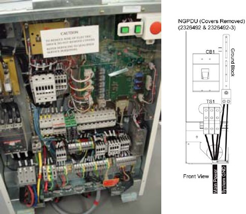
Figure 3. PDU Power Connections
2 System Ground Connection
Procedure
 warning
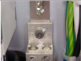
- Connect the ground wire (green with a yellow stripe) from the
table/gantry raceway ground bus to the system ground lug in the PDU.
Figure 4. PDU System Ground Connection
3 Warning Light Configuration & Connection
Procedure
- Warning light is controlled by signals from the system.
- This step is site-specific. The PDU by default is configured
for no external warning light connection. If you have external warning
lights, see Figure 5 for proper connection.
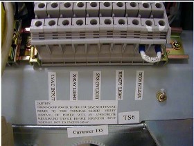
Figure 5. Typical TS6 Warning Light & Door Interlock Connections
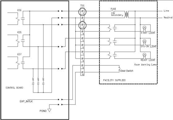
It is recommended that you use the four (4) wire method of adding an x-ray warning light to a room, as shown in Figure 5. When using this method, you:
-
Minimize EMC interference.
-
Increase contact life of the relay used in the PDU.
-
4 Door Interlock Connections
Procedure
- notice
- Door interlocks are used to prevent x-rays from being generated
when the scan room door is open.
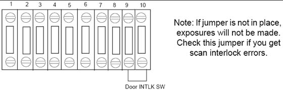
The door interlock circuitry in the PDU is shipped from the factory engaged. This means the system cannot generate x-ray until disengaged. A short must exist between pins 9 & 10 for x-ray to be generated. Using a small piece of wire, short pins 1 and 2 together. See Figure 6.
This is a dry (No Power) contactor for use by a door interlock.
note:This should be wired according to local code.
Figure 6. Without a Door Interlock
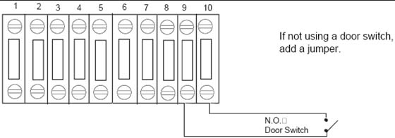
- To use the system with a door interlock, wire a normally open
switch between pins 1 & 2 that is attached to the interlock.
Figure 7. With a Door Interlock
 |
Finalization
No finalization steps.