- Topic ID: id_15460379
- Version: 2.0
- Date: Nov 8, 2018 1:38:35 AM
Slipring Power Supply Replacement
Prerequisites
Overview
This procedure defines the steps necessary to replace the slip ring 15V power supply.
Procedure
- Remove gantry left side cover.
Refer to
- Turn off the gantry Axial Drive, HVDC and 120 VAC switches on the service panel. Power down the console and perform LOTO procedures to lock out power on the gantry.
- Remove the right side top cover to aid in access to the power supply.
- The gantry slip ring power supply is located on a tray on the
right side of the gantry behind the service switch panel. See Figure 1.
Figure 1. Slipring Power Supply
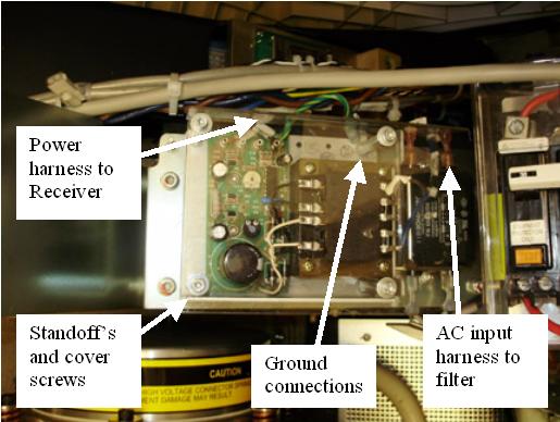
- The power supply is mounted on standoff's connected to the tray. The safety cover is also attached to the standoffs. Remove the M6 hex head screws to remove the safety cover.
- Disconnect the output power harness at the slip ring receiver and the AC input power lugs at the filter. Reference Figure 1. Remove any cable ties if necessary.
- Remove the standoff that attaches the ground wires. Note that there are two ground wires.
- Remove the other standoffs, and then remove the power supply.
- Install the new power supply and attach with the standoff's. Make sure both ground lugs are attached under the standoff as removed. Reference Figure 1. Use the referenced illustration for the subsequent steps.
- Connect the power harness to the slip ring receiver and replace any cable ties previously removed.
- Connect the AC power harness lugs to the filter assembly.
- Install the power supply safety cover.
- Remove the A1 Lockout/Tagout. Turn ON the gantry 120 VAC service switch, and power up the console.
Finalization
- With a DVM, check the DC voltage on the supply to make sure it is 15V +/- 1V nominal to the receiver.
- Turn off the gantry 120 VAC service switch and install the gantry top cover.
- Enable 120 VAC HVDC and Axial Drive service switches from the service switch panel. Press the table drives enable button on the lower right corner of the service switch panel.
- Install the gantry right side cover.
- Perform a System Scanning Test from the Functional Checks menu of the service manual to ensure system operation.