- Topic ID: id_15460643
- Version: 2.0
- Date: Nov 8, 2018 1:36:21 AM
Remove Shipping Brackets and Table Dollies
Prerequisites
1 Remove the IMS Shipping Lock
Procedure
- Remove the right top cover of the table.
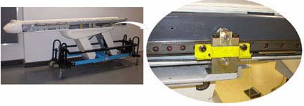
- A yellow shipping lock is located on the right side of the table.
- Unscrew the two bolts and remove the shipping lock.
Figure 1. IMS Shipping Lock
- Re-install the table side cover. See section on Table Cover Installation.
2 Remove Gantry Tilt Bracket
Procedure
 caution
- Remove the M12 bolts using a 10 mm Hex wrench. (See Figure 2.)
Figure 2. Gantry Tilt Bracket Removal
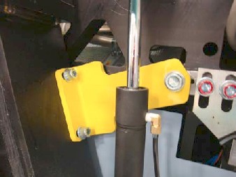
- Loosen the M16 bolt 1-2 turns and check the gantry tilt bracket;
it should be loose to the touch. If the tilt bracket is loose, continue
with step 3.
-
If the tilt bracket is loose, proceed to Step 3.
-
If the tilt bracket is NOT loose, check the hydraulic connections for leaks or lack of fluid. You must wait until the system can be energized to use the tilt controls to relieve the load on the tilt bracket prior to removal. Do not use force to remove the bracket.
-
- If the bracket feels loose, remove the M16 bolt using a 14 mm Hex wrench.
- Remove the bracket.
- Reinstall the gantry rear covers and the scan window.
- Store the brackets in the service cabinet.
3 Remove Table Shipping Dollies
Refer to Figure 3 for the location of items in the table dolly.
Procedure
- Remove one, long side (stabilizer) rail, using the quick disconnect pins. There is one pin on each end of the bar.
- Carefully slide the bar out and place the bar on the side, out of the traffic area.
- Use the 19 mm wrench or 14 mm hex wrench to remove the bolts on each side of the smaller front table attachment bracket. Remove the quick release pins from each side. Remove the bracket.
- Use the 19 mm wrench or 14 mm hex wrench to remove the bolts on each side of the larger rear table attachment bracket and transporter base. Remove the quick release pins from each side. Remove the bracket.
- Remove the quick release pin from each dolly end. Remove support
rail and move it out of the traffic area.note:
Make sure you take off the same side as the stabilizer rail.
- Pull the dolly assembly off the opposite side away from the table.
- Reassemble the dolly for transportation.
Figure 3. Table Shipping Dollies
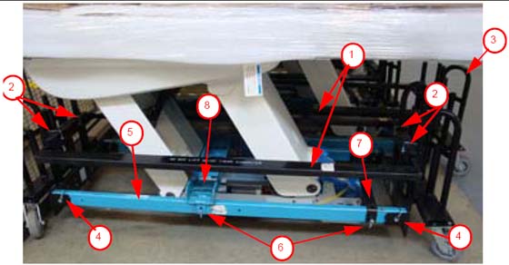
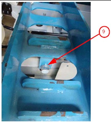
Figure 4. Close-up of table base connection
Finalization
No finalization steps.