- Topic ID: id_15460474
- Version: 6.0
- Date: Jan 20, 2020 8:35:01 PM
Power Pan Bulkhead Filter Assembly Replacement
Prerequisites
Overview
This procedure replaces the Power Pan Bulkhead Filter Assembly. See Figure 1. The "BSD 120V PowerPan with PET and GOP output outlet added" replacement part is referred to as the Power Pan Bulkhead Filter Assembly in this procedure.
Figure 1. Power Pan Bulkhead Filter Assembly Location
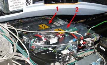
| 1 | AC Power Distribution and Circuit Breaker Assembly |
| 2 | Power Pan Bulkhead Filter Assembly |
1 Prepare System
Procedure
- Tilt the gantry all the way back for easier access to the components in the base of the gantry.
- Make sure to follow all Lockout/Tagout requirements while performing this procedure. Refer to Equipment Service - Lockout-Tagout-PPE procedure.
- Remove covers as needed.
2 Power Pan Bulkhead Filter Assembly Removal
note:
All cables disconnected in this procedure are external to the Power Pan Bulkhead Filter Assembly. Make sure cables are labeled for re-installation or document cable placement.
Procedure
- Disconnect external Ethernet and fiber optic cables from Power Pan Bulkhead Filter Assembly.
- Disconnect all external power cables from TS1, TS2, and TS3.
- Remove four hex bolts securing Power Pan Bulkhead Filter Assembly.
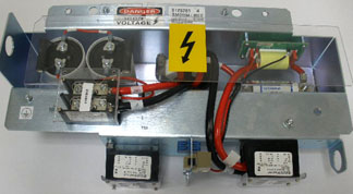
- Lift and remove Power Pan Bulkhead Filter Assembly from system.
See Figure 2.
Figure 2. Power Pan Bulkhead Filter Assembly
3 Power Pan Bulkhead Filter Assembly Re-Install
Procedure
- Place Power Pan Bulkhead Filter Assembly into base of CT Gantry.
- Reconnect external power cables to TS1, TS2, and TS3.
- Reconnect external ground wires.
- Reconnect Ethernet and fiber optic cables.
4 Restore System
Procedure
- Install all removed covers.
- Remove all installed Lockout/tagout devices.
- Restore power to the system. Refer to Equipment Service - Lockout-Tagout-PPE procedure.
5 Finalization
Procedure
- Perform a System Scanning Test from the Functional Checks menu of the service manual to ensure system operation.