- Topic ID: id_15460305
- Version: 2.0
- Date: Nov 8, 2018 1:37:02 AM
Meter Verification
Prerequisites
Overview
This document provides the necessary steps to verify the Generator internal kV and mA metering circuitry calibration.
1 Preparation
Procedure
- Move table to longitudinal home position.
- Remove gantry right side cover.note:
(For Liquid Bearing Tube) Before performing Step 3, if the TubeCare indicator is in the Green zone, wait until the indicator is in the Yellow or Blue zone, then use rotor_ctrl -stop to stop rotor.
- Turn off HVDC ENABLE, AXIAL DRIVE ENABLE and 120VAC ENABLE switches on Service Switch Panel.
- Rotate gantry such that Inverter large cover is accessible.
- Remove Inverter large cover.
2 mA Meter Verification
Procedure
- Complete Preparation steps (See Sections 4.1).
- Wearing a ground connected protective ESD device, remove jumper
from Inverter Test Point TP17. (Item 1 in Figure 1)
Figure 1. Inverter Meter Test Points
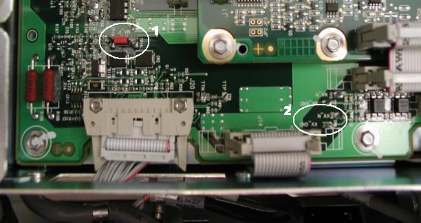
- Clip Digital Multimeter mADC signal RED lead to Inverter Test Point TP19 and Digital Multimeter common BLACK lead to Inverter Test Point TP15. (Item 1 in Figure 1)
- Turn on 120 VAC ENABLE switch on Service Switch panel.
- Press ESTOP RESET on Service Switch panel and wait until scan hardware is reset.
- Turn on Digital Multimeter and select mADC setting.
- Select DIAGNOSTICS from Service Desktop.
- Select GENERATOR TOOL – JEDI, or X-RAY GENERATION, GENERATOR TOOL – JEDI.note:
Refer to Illustrations 4 (Unsuccessful) and 5 (Successful) for examples that are displayed on the CSD.
- Click METER VERIFICATION.
Figure 2. Meter Verification Unsuccessful test
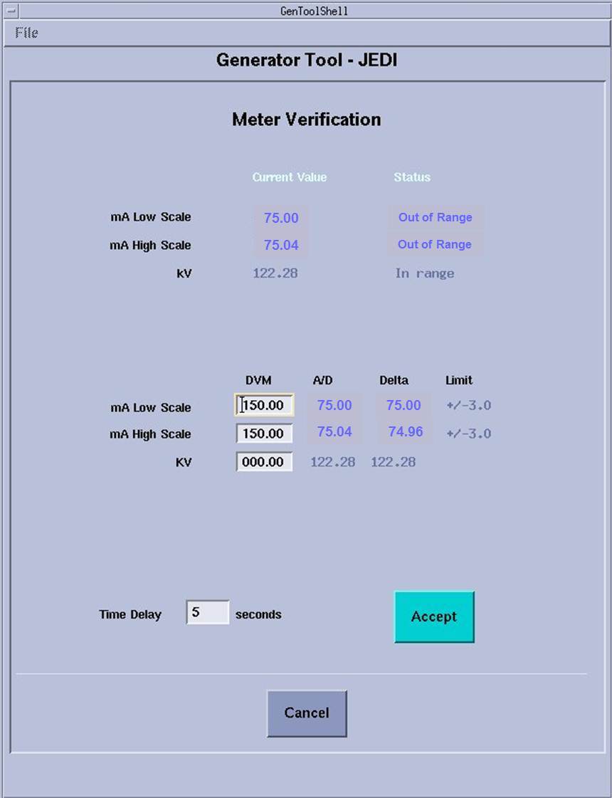
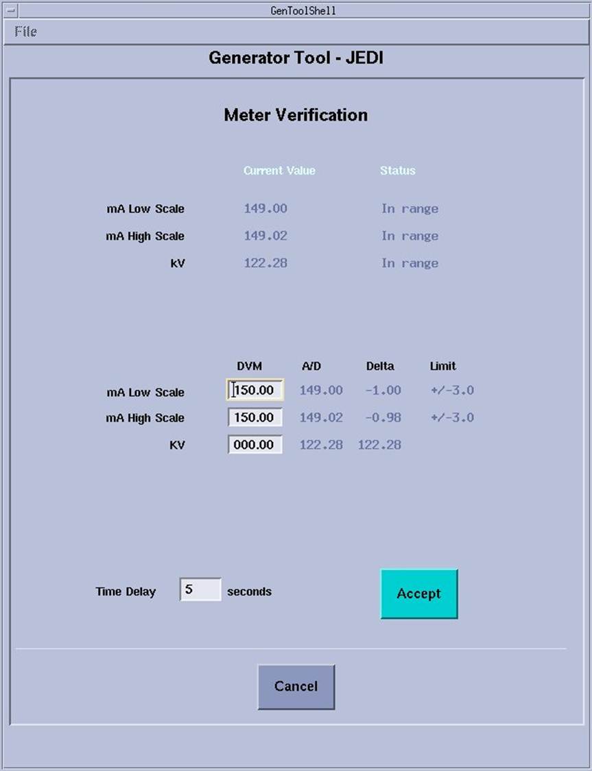
Figure 3. Meter Verification Successful test
 note:
note:Time Delay is defaulted to 5 seconds. Time delay can be changed to give sufficient time to get to Digital Multimeter.
- Click ACCEPT and walk to Digital Multimeter.
- Observe highest mA reading attained from Digital Multimeter,
to one decimal place.
EXAMPLE: 147.3
note:Measured value should be around 150 mA.
- Enter measured mA value in MA LOW SCALE DVM edit box and press ENTER. note:
Measured mA value will appear in the MA HIGH SCALE DVM edit box automatically.
- Verify MA LOW SCALE DELTA is within MA LOW SCALE LIMIT, and MA HIGH SCALE DELTA is within MA HIGH SCALE LIMIT.note:
If Delta values are outside limits, replace Inverter and retest.
- Record results in the appropriate GE e4879 Installation form, GE e4879 Certified Component Verification form, or GE Data Report Planned Maintenance Schedule form.
- Turn off Digital Multimeter.note:
(For Liquid Bearing Tube) Before performing Step 16, if the TubeCare indicator is in the Green zone, wait until the indicator is in the Yellow or Blue zone, then use rotor_ctrl -stop to stop rotor.
- Turn off 120 VAC ENABLE switch on Service Switch panel.
- Wearing a ground connected protective ESD device, remove leads from Inverter Test Points TP15 and TP19 and install jumper to Inverter Test Point TP17.
3 kV Meter Verification
Procedure
- Complete Preparation steps (See Sections 4.1).
- Wearing a ground connected protective ESD device, clip Digital Multimeter VDC signal RED lead to Inverter Test Point TP6 (KV_N) and Digital Multimeter common BLACK lead to Inverter Test Point TP8 (KV_GND). (Item 2 in Figure 1)
- Turn on 120 VAC ENABLE switch on Service Switch panel.
- Press ESTOP RESET on Service Switch panel and wait until scan hardware is reset.
- Turn on Digital Multimeter and select VDC setting.
- Click ACCEPT in Meter Verification window and walk to Digital Multimeter.
- Observe highest volts reading attained on Digital Multimeter.
- Calculate measured kV value by multiplying Digital Multimeter value by -10.
- Enter measured kV value in KV edit box and press ENTER.
- Record results in the appropriate GE e4879 Installation form, GE e4879 Certified Component Verification form, or GE Data Report Planned Maintenance Schedule form.
- Click CANCEL in Meter Verification window .
- Click DISMISS in Generator Tool - JEDI window.
- Turn off Digital Multimeter.note:
(For Liquid Bearing Tube) Before performing Step 14, if the TubeCare indicator is in the Green zone, wait until the indicator is in the Yellow or Blue zone, then use rotor_ctrl -stop to stop rotor.
- Turn off 120 VAC ENABLE switch on Service Switch panel.
- Wearing a ground connected protective ESD device, remove leads from Inverter Test Points TP6 and TP8.
4 Finalization
Procedure
- Install Inverter large cover.
- Position Inverter large cover over Inverter opening.
- Starting with the lower left hand corner captive screw and following
the order shown in Figure 4, align each captive screw to the hole in the
Inverter chassis and turn the screw clockwise until the screw engages
with the hole.note:
Captive Screw misalignment and/or over tightening could break the screw and get lodged in the inverter chassis causing irreparable damage. In the event that this happens, replace Inverter.
note:Complete this step for all six captive screws before performing step 1c.
Figure 4. LightSpeed VCT Inverter Large Cover Installation
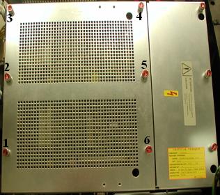
- Starting with the lower left hand corner captive screw and following the order shown in Figure 4, torque each captive screw to 0.45 N-m or 4.0 lbf-in.
- Turn on 120 VAC ENABLE, AXIAL DRIVE ENABLE and HVDC ENABLE switches on Service Switch Panel.
- Press ESTOP RESET on Service Switch panel and wait until scan hardware is reset.
- Install gantry right side cover.
- Store data form with system history records.