- Topic ID: id_15460652
- Version: 3.0
- Date: Jun 15, 2020 10:51:39 PM
Mark Equipment Anchoring Locations
Prerequisites
Overview
Procedure
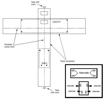
- Lay out the two (2) pieces of the floor template (GT table: 5111499). Start with the table template, then place the gantry template over the top of the table template. Align them per the GE print.
- Tape the templates together, making sure that the table and gantry center lines are matched. Then tape the template to the floor.
- Recheck the position of the gantry in the room per the GE print. If everything matches the GE print, continue. If not, realign the templates to match the print.
- Make sure there are no potential clearance issues. If there
are floor obstructions, such as conduits or old anchors, be sure to
cut them flush to the floor to prevent the gantry from resting on
them. Also, be sure there is at least 102 mm (4 in.) of clearance
between any existing floor penetration and the new gantry position.note:
There must be clear space without obstructions in order to:
-
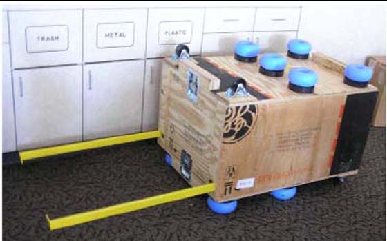
Change major components, with access to the gantry tube-change (RH) side (See Figure 1).
-
Allow space for front and rear cover removal
note:See Service Clearance Section found in the Pre-Installation Manual.
Figure 1. Gantry Tube Change Cart
-
- Prior to removing this template, check floor levelness, as shown in Figure 2.
- Position the laser from the install kit on the template behind the table base and turn it on to project a horizontal beam across the floor template area.
- Measure the distance from the floor to the laser line at each
bolt hole location on the template and record the measurements. Use
the measurements to verify the floor is within specification. The
floor must meet the minimum levelness specification: 6 mm (1/4 in.)
over 3.5 m (10 ft.) between the table and gantry.
Figure 2. Check Floor Level
- notice
- Check with the customer for approval of the gantry/table placement.
Figure 3. Center Line with Marks
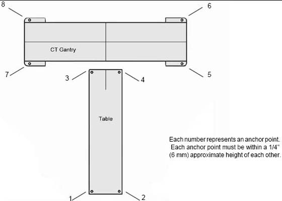
- Use a center punch to mark hole centers for each of the eight (8) leveling pad/anchor locations. Before moving on to the next step, see Step 11 and its note for an alternative method.
 caution
- Remove the floor template.
- Cut tiles (or other resilient flooring) around all holes punched
in the template for the gantry and table.note:
A fast way to remove flooring is to use a 4 in. hole saw with a 1/4 in. masonry bit to cut through the flooring at each leveler pad location.
- Some sites require sealing of the floor penetrations after the flooring is removed. If this site does, use RTV or other sealant to seal the floor covering as necessary.
- notice
- Snap a chalk line using the marks that were made on the tape at the ends of the table template.
 |
 |
Finalization
No finalization steps.