- Topic ID: id_15460910
- Version: 4.0
- Date: Jan 20, 2020 8:32:16 PM
Link Bar Assembly Replacement
Prerequisites
Overview
1 Cradle / IMS Compensation for Up/Down Movement
Procedure
- Raise the Table to maximum height.
- Move the Cradle and IMS to OUT limit position.
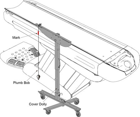
- Hang a plumb bob using a cover dolly.
- Mark a position on the top cover of the Table at string of the
plumb bob.
Figure 1. Plumb Bob and Cover Dolly
- Lower the table to ISO-280mm.
- Verify that the difference in position between the top cover
marking and the string position is within 1.0 mm (0.04 in).
If the difference is not within specification, record the difference value, and replace the link bar assembly refer to Link Bar Assembly Replacement.
2 Link Bar Assembly Replacement
2.1 Link Bar Assembly Removal
Procedure
- Raise the Table to maximum height.
- Remove power from Table by turning off 120VAC, Axial Drive and HVDC switches on Service Switch Panel.
- Remove the following Table covers:
-
IMS Side Cover (Right)
-
IMS Rear Cover
-
Front/Rear Side Plate (Right/Left)
-
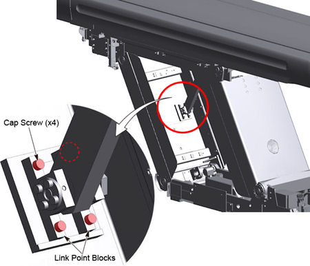
- Remove four cap screws from the link point block.
Figure 2. Link Point Block Removal
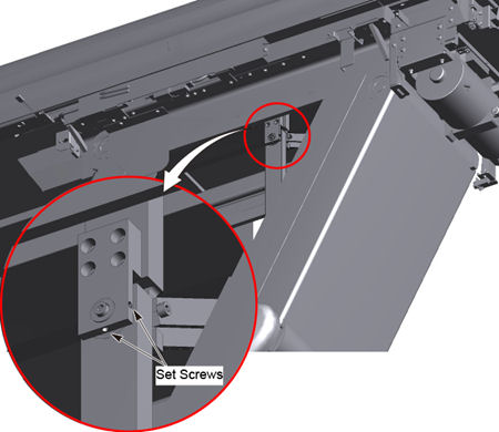
- Loosen two set screws at the upper portion of the link bar.
Figure 3. Set Screws Loosening
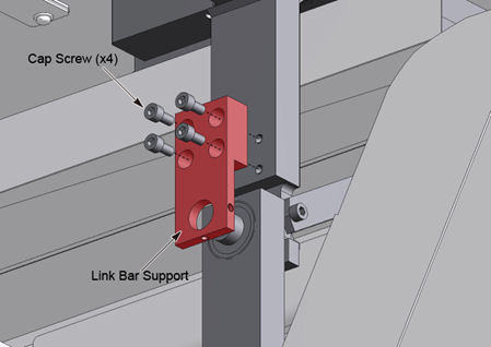
- Remove the link bar support by unscrewing four cap screws.
Figure 4. Link Bar Support Removal
- Disengage the link bar assembly from the IMS base by unscrewing
its pin add link, and remove the link bar assembly from the table.
Figure 5. Pin Add Link
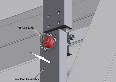
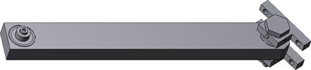
Figure 6. Link Bar Assembly
2.2 New Link Bar Assembly Installation
Procedure
- Engage the new link bar assembly to the IMS base using the pin add link.
- Install the link bar support using four cap screws.
- Tighten two set screws.
- Choose a proper shim according to the following, and put the
shim on the inside edge of the mounting base.
Figure 7. Shim and Mounting Base
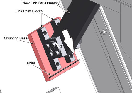
- Push the link point blocks against the shim and the inside edge
of the mounting base, and tighten four cap screws to mount the link
point block on the mounting base.
Power up the Table from the Service Switch Panel.
- Perform Cradle/IMS Compensation check refer to Cradle / IMS Compensation for Up/Down Movement , and verify that the difference in position between the marking and the string position is within 1.0 mm (0.04 in).
3 Finalization
Procedure
- Turn off all 3 switches (Axial Drive, HVDC, 120VAC), and re-install the Table covers.
- Power up the Table from the Service Switch Panel.
- Verify that the table movement is operating normally.