- Topic ID: id_15460908
- Version: 2.0
- Date: Nov 8, 2018 1:36:39 AM
LightSpeed VCT Xtream HD Console Upgrade
Prerequisites
Overview
This document describes and illustrates the steps necessary to upgrade a LightSpeed VCT GOC5 Operator Console with an Xtream HD (GOC6 Series with VeRB) Operator Console.
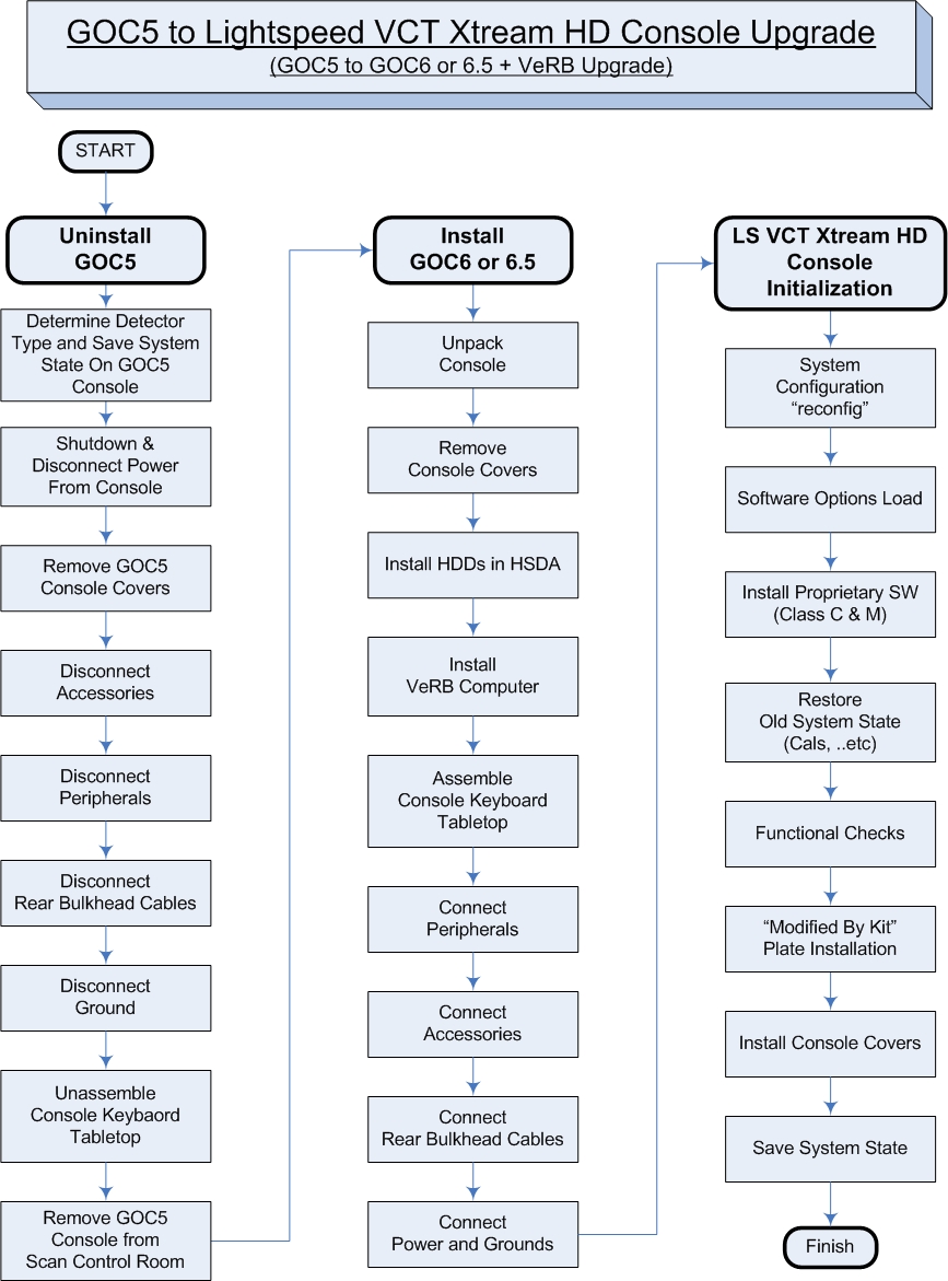
Refer to the flowchart in Figure 1 for the overall upgrade process. .
Figure 1. GOC5 to LightSpeed VCT Xtreme HD Console Upgrade (GOC5 to GOC6 Series + VeRB Upgrade) Flowchart
Please review Section 3.5, Required Conditions, before proceeding with this upgrade procedure.
1 Inventory Upgrade Kits
Procedure
- Before starting upgrade and console disassembly, check contents of Upgrade Kit to make certain all supplied parts are present and have not been damaged in shipping. (Refer to Section 3.3, “Replacement Parts”)
- If the existing GOC5 Operator Console has a SCSI MOD Archive
Peripheral Tower, a new version of the Option should have been ordered
with the Xtream HD Console Upgrade.
2 Identify Detector/DAS type
There are three types of VCT Detectors/DAS released, VDAS (Sherlock Detector), HDAS (HALO Detector), and HDAS_Saturn_64 (Saturn Detector). They are identified on the Common Service Desktop Home page "Data Acquisition System" type listed as VDAS, HDAS, or HDAS_SATURN.
Procedure
- Before un-installing GOC5 Console, identify which Detector/DAS type is present with system being upgraded.
- Look at the Common Service Desktop home page for the DAS type entry. If the DAS type = VDAS64 or HDAS64, then you have a Sherlock or HALO detector and system software will need to be reloaded after installing the new Xtream HD Console. The Lighspeed VCT Xtream HD GOC6 Series console comes loaded for the DAS type = HDAS_SATURN_64, which is the Saturn detector.
- Record the DAS type now, to be used later in the Console Initialization
section.
3 Uninstall GOC5 Operator Console
3.1 Save System State on GOC5 Console
Procedure
- Save a new System State in accordance with Software – GOC5 > Software Installation > System State Save & Restore in the LightSpeed VCT Service manual supplied with this upgrade.
- Note that the above System State Save & Restore procedure is applicable to GOC5 as well.
3.2 Shutdown and Disconnect Power on GOC5 Operator Console
Procedure
- Select one of the following methods to power off the Operator
Console:
- If Applications are running, click on Shut Down and select Shutdown.
- If Applications are down, open a Unix Shell using the Toolchest.
Type:
{ctuser@hostname} haltENTER
The Operator Console Monitor will display a System Halted message when it is acceptable to power off the Operator Console.
- Power OFF the Operator Console at the front panel switch.
- Remove the Console’s incoming Twist-N-Lock Power Cable from rear of GOC5 Console.
- Perform Lockout / Tagout as described in Safety – Equipment Service – Lockout / Tagout / PPE in the LightSpeed VCT Service Manual.
3.3 Remove GOC5 Console Covers
Procedure
- Move the console away from the wall to allow clear access around the console.
- Remove the console front and rear covers and set aside.
3.4 Disconnect Accessories/Options on GOC5 Operator Console
Disconnect the Accessories in the following table from the GOC5 Console. Follow table instructions for disposition of items removed.
Procedure
- Remove the Monitors from the GOC5 Console by disconnecting the Video Cables from the Host Computer, and Power Cables from the Console Outlet Box inside the GOC5 Console. These cables will be returned with the GOC5 Console.
- Disconnect and remove the Trackball from the GOC5 Console.
- Disconnect and remove the Barcode Reader (if so equipped) from the GOC5 Console.
- Disconnect and remove the Remote Monitor Video Amp/Splitter (if so equipped) from the GOC5 Console. Make sure that all cable connections are labeled. Disconnect the Video Amp/Splitter power cable from the Console Outlet Box inside the GOC5 Console. Keep these cables that were connected to the Video Amp/Splitter, as they will be needed for new GOC6 Series Console.
- Disconnect and remove the Digital DASM (if so equipped) from the GOC5 Console. Make sure that all cable connections are labeled. Disconnect the SCSI I/F cable from the Host Computer. Disconnect the Digital DASM power cable from the Console Outlet Box inside the GOC5 Console. Keep these cables, as they will be needed for new GOC6 Series Console.
- Disconnect and remove the Service Modem (if so equipped) from the GOC5 Console. Make sure that all cable connections are labeled. Disconnect the RS232 cable from the Host Computer. Disconnect the Service Modem power cable from the Console Outlet Box inside the GOC5 Console. Keep these cables, as they will be needed for new GOC6 Series Console.
3.5 Disconnect Peripherals on GOC5 Operator Console
Disconnect the following peripherals in the following table from the GOC5 Console. Follow table instructions for disposition of items removed.
Procedure
- Disconnect and remove SCSI Peripheral Tower from GOC5 console.
- Disconnect the SCSI Cable from the Host Computer and Power Cable
from Console Outlet Box inside the GOC5 console.
These cables will be returned with GOC5 Console.
- Disconnect and remove the SCIM Assembly from GOC5 console.
- Disconnect the SCIM Cable from the under side of the SCIM Assembly.
- Disconnect and remove the Mouse from the GOC5 console.
- Disconnect the Keyboard PS2 cable from the Upper Bulkhead Panel.
- Disconnect and remove the Keyboard from the GOC5 console.
- Disconnect the Keyboard PS2 cable from the Upper Bulkhead Panel.
3.6 Disconnect Rear Bulkhead Cables on GOC5 Operator Console
Procedure
- Disconnect all cables connected to the Rear Bulkhead Panel on the GOC5 Console. These include the Network, Fiber Optic Link, and Gantry DB25 Cables.
- Make sure that all cables are clearly labeled as to their function and source.
3.7 Disconnect Ground Cables on GOC5 Operator Console
Procedure
- Remove the Scan Room Patient Reference Ground cable from GOC5 console.
- Make sure cable is clearly labeled as to function and source.
3.8 Disassemble Keyboard Tabletop on GOC5 Operator Console
Procedure
- Remove the Operator Console Keyboard Table Top Assembly and
Support Arms from the GOC5 Console.
Keep track of all hardware (bolts, washers).
- Locate this hardware with the Keyboard Tabletop Assembly by placing the hardware in a small plastic bag and taping it to the tabletop.
3.9 Remove GOC5 Operator Console from Scan Control Room
Procedure
- Remove the GOC5 Operator Console from the Scan Control Room.
- Remove any accessory and peripheral items being returned to
make room for the GOC6/6.5 Console.
4 Install GOC6 or GOC6.5 Operator Console
4.1 Unpack Console
Procedure
- Refer to Installation > Mechanical Installation > Operator
Console Installation in the LightSpeed VCT Service Manual
supplied with the upgrade and follow the unpacking instructions.note:
Take care not to damage or throw out any of the packing material. This will be used to repack the GOC5 Console for return.
- Move the Console into the Scan Control Room.
4.2 Remove Console Covers
Procedure
- Refer to Installation > Mechanical Installation > Operator Console Installation in the LightSpeed VCT Service Manual supplied with the upgrade and follow the Console Cover Removal instructions.
- Do not install the Keyboard Tabletop Assembly at this time.
4.3 Install Hard Disk Drives in HSDA
Procedure
- Locate the shipping boxes that contain the HSDA Drives with Trays.
- Open the shipping boxes and notice that each Drive Tray is now
be labeled with a number. This number corresponds to the HSDA Bay
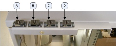
location where the Drive Tray should be installed. (See Figure 2)
Figure 2. Drive Bay Location for HSDA1 (Console Front)
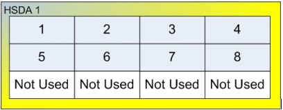
- Insert each of the eight (8) Drive Trays into their proper bay
location.note:
By placing Drive Trays in their designated HSDA bay locations, recreating the Scan Data Logical Disk Array will not be required.
- Make sure all Drive Trays are securely inserted and Drive Tray Doors are closed and locked.
4.4 VeRB/VeRB2 Computer Install
(Note: VeRB Computer used in GOC6, VeRB2 Computer used in GOC6.5)
Procedure
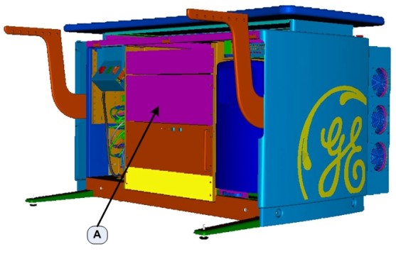
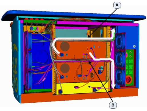
- At the front of the Console, remove the Rack Blank Panel (Item A in Figure 3) immediately above the DIG Computer. The Rack
Blank Panel is no longer needed. Dispose of it properly.
Figure 3. Console Rack Blank Panel Location
 note:
note:Save the four (4) 5mm socket cap bolts and washers.
- Remove the VeRB Computer (5255299-30 For GOC6 or 5255299-31 for GOC6.5) from the shipping container and check that all packing material has been removed and is not blocking intake fans or ventilation grills on the computer chassis.
- Lift and slide the VeRB Computer in the front of the console, sliding the VeRB Computer on the two rack guides already installed in the console rack. Push the VeRB Computer fully into the console rack until it is flush with the front of the console rack.
- Mount the VeRB Computer to the console rack utilizing the four (4) 5mm socket cap bolts and washers removed earlier. Torque to 4.6 N-m.
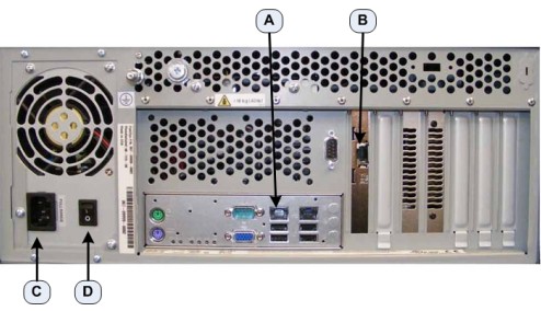
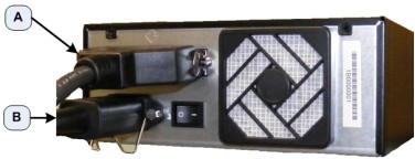
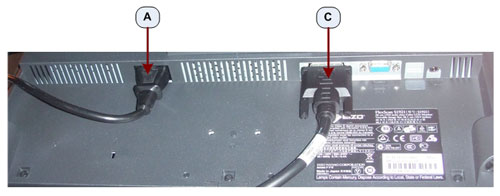
- At the rear of the console, plug the VeRB Computer Power Cable
(5314704) into the VeRB Computer. (Item C in Figure 4)
Figure 4. VeRB Power and Network Connections
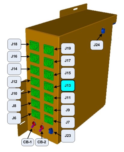
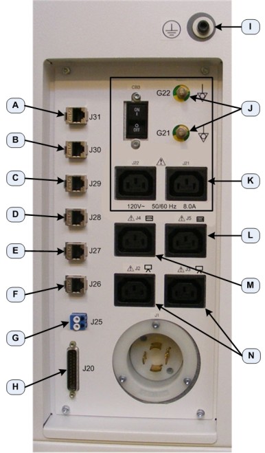
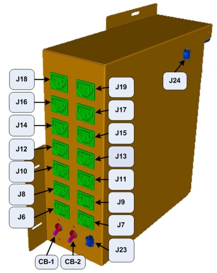
- Label the other end of the VeRB power cord “VeRB J13” using the supplied Cable Labels. Insert this end of the VeRB Computer Power Cable into the console cabinet, along the right side top of the rack, to the Power Distribution Box. (See Figure 6)
- Plug this end of the VeRB Power Cord into J13 on the Power Distribution
Box. (See Figure 5)
Figure 5. J13 - VeRB Power Cable Location on Power Distribution Box
- Run the power cable along the cable tray (Item A in Figure 6), directly above the VeRB Computer. Using several tie wraps, secure
the VeRB Power Cable to the cable tray.
Figure 6. VeRB Power and Network Cable Routing
- At the rear of the console, plug the VeRB Computer Network Cable (5313765) into the VeRB network port. (Item A in Figure 4) Label this end of the network Cable “VeRB Eth 6” using the supplied Cable Labels (5316747-3).
- Label the other end of the VeRB Computer Network Cable “Eth 6 VeRB” using the supplied Cable Labels. Insert this end of the VeRB Computer Network Cable into the console cabinet, along right side bottom of the rack, to the Console Network Switch (CNS). (See Figure 6)
- At the rear of the console, plug the VeRB Computer RMM Network Cable (5313765) into the VeRB RMM network port. (Item B in Figure 4) Label this end of the network Cable “VeRB RMM Eth 5” using the supplied Cable Labels.
- Label the other end of the VeRB RMM Network Cable “Eth 5 VeRB RMM” using the supplied Cable Labels. Insert this end of the VeRB Computer Network Cable into the console cabinet, along right side bottom of the rack, to the CNS. (See Figure 6)
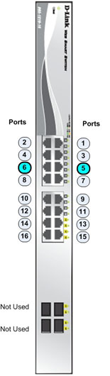
- Connect the VeRB Network Cables into their respective ports
on the CNS. (See Figure 7or Figure 8 depending on Console Network Switch version.)
Figure 7. VeRB Network Cable Connections on Console Network Switch (5263798)
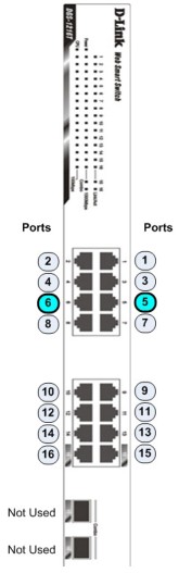
Figure 8. VeRB Network Cable Connections on Console Network Switch (5263798-2)
- Run the Network Cables along the cable tray (Item B in Figure 6), directly below the VeRB Computer. Using several tie wraps, secure the VeRB Network Cables to the cable tray.
4.5 Assemble Console Keyboard Tabletop
Procedure
- Refer to Installation - Mechanical Installation - Operator Console Installation in the Lightspeed VCT Service Manual supplied with the upgrade.
- Follow the Console Keyboard Tabletop installation instructions.
4.6 Connect Peripherals
Procedure
- Connect the USB DVD Peripheral Tower to GOC6/6.5 console.
- Connect the USB Cables coming from the Host Computer into the
rear of the DVD Peripheral Tower. (See Figure 9)
Figure 9. DVD Peripheral Tower Connections
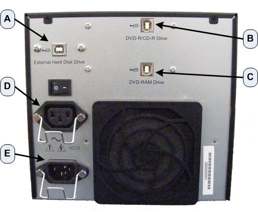
- Connect the DVD Peripheral Tower Power cable to the rear of
the DVD Peripheral Tower (Item E in Figure 9) and connect
the other end of the Power Cable into the Lower Rear Bulkhead Panel.
(Item L in Figure 10)
Figure 10. Lower Rear Bulkhead Panel Connections
- Connect the MOD Peripheral Tower (if this option is supplied with the upgrade) to the GOC6/6.5 Console.
- Connect the SCSI Cable coming from the Host Computer into the
rear of the MOD Peripheral Tower. (Item A of Figure 11)
Figure 11. MOD Peripheral Tower (Optional) Connections
- Connect the MOD Peripheral Tower Power Cable into the MOD Peripheral Tower (Item B in Figure 11), and insert the other end of the Power Cable into the DVD Peripheral Tower. (Item D in Figure 9)
- Connect the SCIM Assembly to the GOC6/6.5 Console by inserting
the SCIM Interface cable into the SCIM Assembly. (Item A in Figure 12)
Figure 12. SCIM Assembly Connections
- Connect the Mouse to the GOC6/6.5 Console by plugging the Mouse
into the Upper Bulkhead Panel. (Item B in Figure 13)
Figure 13. Upper Bulkhead Panel Connections
- Connect the Keyboard to GOC6 / 6.5 Console by passing the Keyboard
USB Cable through the SCIM Assembly (Item B in Figure 12) and plugging the Keyboard into the Upper Bulkhead Panel. (Item C in Figure 13)
4.7 Connect Accessories
Procedure
- Connect the Monitors to the GOC6 / 6.5 Console by inserting
the Video cables (Item B or C in the following
Illustrations) into the Monitors coming from Host Computer.
Figure 14. NEC 1990SXi LCD Display / Image Monitor Connections GOC6 & GOC6.5
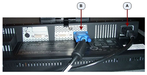
Figure 15. EIZO S1921-X LCD Display / Image Monitor Connections GOC6 & GOC6.5
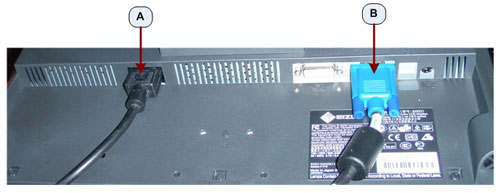
Figure 16. NEC 1990SXi LCD Prescription / Scan Monitor Connections GOC6
Figure 17. EIZO S1921-X LCD Prescription / Scan Monitor Connections GOC6
Figure 18. NEC 1990SXi LCD Prescription / Scan Monitor Connections GOC6.5
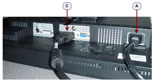
Figure 19. EIZO S1921-X LCD Prescription / Scan Monitor Connections GOC6.5
- Run the Power cables from the Monitors (Item A in the above Illustrations) to the Console’s Lower Rear Bulkhead
Panel. (Item N in Figure 10).
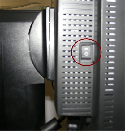
- For NEC 1990SXi LCD Monitors, make sure that the Monitor Power
Switch (Figure 20) has been turned ON.
Figure 20. Monitor Power Switch
- Connect the Trackball to the GOC6/6.5 Console by plugging the Trackball into the Upper Rear Bulkhead Panel. (Item D in Figure 13)
- Connect the Bar Code Reader (if so equipped) to the GOC6/6.5 Console by plugging the Bar Code Reader into the Upper Rear Bulkhead Panel. (Item A in Figure 13)
- Place and connect the Video Amp/Splitter (if so equipped). Connect
the Video Amp/Splitter power cable to the Console Outlet Box inside
the GOC66.5 Console. (See Item J10 in Figure 21)
Figure 21. Power Distribution Box
Connect the Video cable coming from the Host Computer Right Display and Right Display Monitor Video cable to the Video Amp/Splitter.
- Place and connect the Digital DASM (if so equipped). Plug the Digital DASM power cable to the Console Outlet Box inside the GOC6/6.5 Console. (See Item J17 in Figure 21) Connect the SCSI I/F cable coming from the Digital DASM to the Host Computer SCSI Port.
- Place and connect the Service Modem (if so equipped) to the GOC6 Console. Plug the Service Modem power cable to the GOC6 Console Outlet Box. (See Item J11 in Figure 21.) Connect the RS232 cable coming from the Service Modem on the Host Computer Serial Port.
4.8 Connect Rear Bulkhead Cables
Procedure
- Reconnect the Gantry and Network Interface Cables removed earlier from the GOC5 Operator Console.
- See Figure 10 for proper connection locations.
NOTICE: IT IS IMPORTANT THAT NETWORK INTERFACES BE CORRECTLY PLUGGED INTO THEIR RESPECTIVE PORT LOCATIONS.
4.9 Connect Power and Grounds
Procedure
- Connect the Scan Room Patient Reference Ground cable to the rear of the GOC6/6.5 Console. (Item I in Figure 10)
- Connect the Twist-N-lock Power Cable on the GOC6/6.5 Console.
- Remove Lockout/Tagout.
Refer to Safety – Equipment Service – Lockout / Tagout - PPE in the LightSpeed VCT Service Manual supplied with the upgrade, and perform the Lockout/Tagout process in reverse.
- Power On the console and confirm that all computer connections
are receiving power.note:
At this time the GOC6/6.5 console may not properly initialize to full system functionality.
5 Console Initialization
Read this section in its entirety before executing this part of the procedure! In almost every case a Load From Cold will be required to complete the Console Upgrade.
5.1 LFC Preparations
Make note of the following LFC process clarifications:
Procedure
- Refer to DAS type as record in Section 4.2 "Identify Dectector/DAS
type. A VDAS64 or 32 is a “Sherlock” detector, and is
noted in the Parts list as VDAS. The HDAS64 is a HALO detector is
noted in the Parts list as HDAS. The HDAS_SATURN_64 is a Saturn detector,
and is noted in the Parts list as Saturn.note:
LFC is required on SHERLOCK and HALO Detector-based VCT Systems receiving this upgrade. All Saturn Detector-based systems should already be using a GOC6/6.5 Series Console and not be receiving this upgrade.
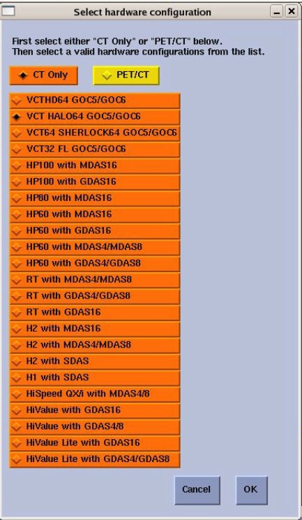
- Manually configure System Type. During the APPS Load Section
of the LFC, do not use
the System State disk from the older GOC5 console or the new GOC6/6.5
console to retrieve System INFO file. System Type must be manually configured during this initial LFC.
Figure 22. Manual System and Console Hardware Configuration
- During the LFC process when executing the LFC Menu, skip the Restore System State step. Items like Cals, Characterization,
and Protocols will be restored after the LFC has been performed.note:
Restore System State in the LFC Menu is an automated process and does not allow for selection of individual categories for restore.
5.2 Load from Cold (LFC) Required on SHERLOCK and HALO Detector-based VCT Systems
Procedure
- Perform GOC6 Series Load from Cold.
Refer to Software GOC6/6.5 > Software Installation Procedures >(xxMWxx.x) GOC6 Series Load From Cold procedure in the LightSpeed VCT Service manual supplied with the upgrade and follow the procedure for loading System Software.
note:Check the Applications software version on the CD shipped with the upgrade, then follow the applicable (xxMWxx.x) Software LFC procedure on the supplied Service Information CD
note:New License Keys will be supplied with Console Upgrade. All old Software License keys from original Customer Order (GOC5) for the system being upgraded will no longer work for the new console. During the ordering process for the Xtream HD Console Upgrade, Sales will need to supply a list of the Options the Customer originally acquired.
- Upon completion of the LFC and reboot of System, perform a Restore
System State. Restore the following files and data from the old GOC5
System State:
-
Protocols
-
Characterization
-
Cals
-
Auto Voice
-
Display Preferences
-
Camera Preferences
-
- Tube Usage Files:
Immediately after restoring System State run the following ConvertTubeUsageFiles command:
-
Open a Unix shell.
-
At ctuser type: ConvertTubeUsageFiles (Note: Case sensitive.)
-
Enter Selection: 4, Done Converting Tube Usage Files!
-
Now perform a Scan Hardware Reset and reboot the system.
-
- Create a final System State Disk
Perform the (xxMWxx.x) System State Save & Restore procedure and save a System State Backup to either DVD-RAM or USB Media.
6 Finalization
Procedure
- Refer to Functional Checks – System Scanning Tests in the LightSpeed VCT Service Manual supplied with the upgrade and perform the tests to confirm proper operation.
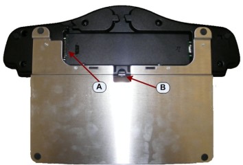
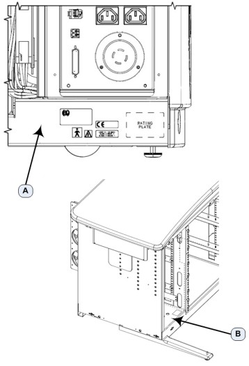
- Attach the VeRB Upgrade “Modified By Kit” plates
(5335238) (Figure 23) alongside the present Rating Plates. (Locations A and B in Figure 24)
Figure 23. Modified By Kit Plate
Figure 24. Modified By Kit Plate Locations
- Reinstall the Console Front and Rear Covers.note:
Refer to Replacement > Console > GOC6/6.5 > Console Cover Removal and Installation in the LightSpeed VCT Service Manual for more details.
- Save a new System State in accordance with Software GOC6/6.5 > Software Installation procedures > System State Save Restore in the LightSpeed VCT Service manual supplied with the upgrade.
- The old GOC5 console has components that are needed to cover
FRU shortages, so PLEASE RETURN THE GOC5 CONSOLE. Follow the normal
local return process to return the GOC5 console.
- Package the GOC5 console with the shipping material from the new GOC6/6.5 console.
- Mark the outside of the box “GOC5 Console.”
- For U.S. sites, call Schenker Heavyweight Return at 866-229-7877
(Option 25), and ship to:
GE Healthcare Renewable Resources
7624 South 10th Street
Oak Creek, WI. 53154