- Topic ID: id_11038814
- Version: 7.0
- Date: Jun 4, 2020 8:06:02 PM
LCD Video Monitor Setup DEL
Prerequisites
Overview
This procedure outlines the process required to set up a NEC, Bigtide, EIZO & HP LCD Display Monitors. If a system has more than one of these monitors, each must be setup. The procedure time listed above is for each monitor. An active video input signal must be connected to each monitor to perform this process.
For an overview of monitor front panel controls and monitor informational messages for the NEC 1990SXi LCD Display Monitor, see NEC 1990SXi On Screen Manager Controls
For an overview of monitor front panel controls and monitor informational messages for the Bigtide HL1916 LCD Display Monitor, see Bigtide HL1916 Screen Manager Controls
For an overview of monitor front panel controls and monitor informational messages for the EIZO S1921-X / S1923–H LCD Display Monitor, see Eizo S1921-X / S1923-H Screen Manager Controls
For an overview of monitor front panel controls and monitor informational messages for the HP E190i LCD Display Monitor, see HP E190i On Screen Manager Controls
1 LCD Display Monitor Connections and Powering Up
Procedure
- Connect the video cable(s) between the Operator Console’s
HOST computer and each monitor’s inputs. See the following Illustrations
for the appropriate LCD Display Monitor.note: Do not use OEM Manufacturer’s supplied video cables.
Figure 1. NEC 1990SXi LCD Display / Image Monitor Connections
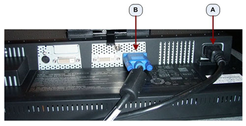
Figure 2. NEC 1990SXi LCD Prescription / Scan Monitor Connections
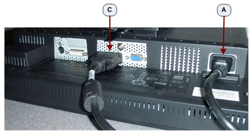
Figure 3. Bigtide HL1916 LCD
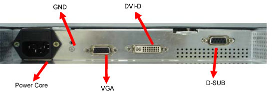
Figure 4. EIZO S1921-X / S1923–H LCD Display / Image Monitor Connections
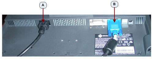
Figure 5. EIZO S1921-X / S1923–H LCD Prescription / Scan Monitor Connections
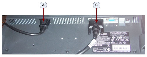
Figure 6. HP E190i LCD Monitor Connections
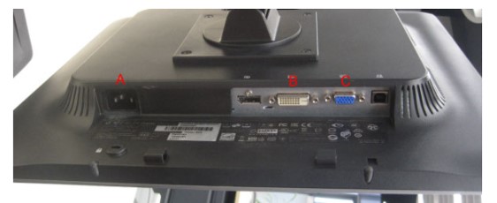
- Connect the AC in line cord from the Operator Console to each
monitor's rear side using the GE supplied console power cord. See
Illustrations above.note: Do not use the OEM Manufacturer's supplied power cord.
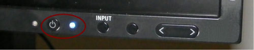
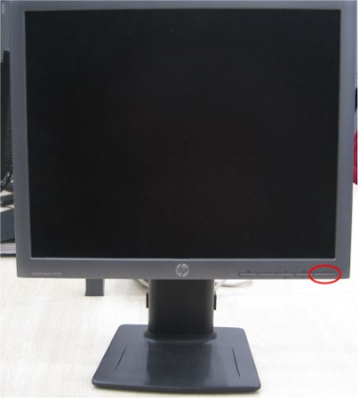
- Apply power to each monitor. Press the power button/switch to
apply power to each monitor. See the following Illustrations.
Figure 7. NEC 1990SXi Power Switch
 note:The NEC 1990SXi has a Main Power Switch and is a true on/off switch. If the switch is in the OFF position, the monitor cannot be turned on using the power button on the front panel.
Figure 8. NEC 1990SXi Main Power Switch
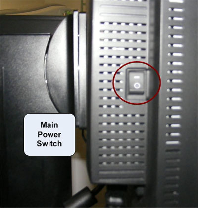
Figure 9. Bigtide HL1916 Power Switch
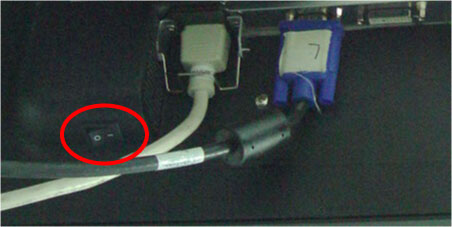
Figure 10. EIZO S1921-X / S1923–H Power Button
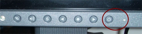
Figure 11. HP E190i LCD Monitor Power Button
2 LCD Monitor Setup and Calibration
The LCD monitor comes configured with OEM default settings and must be properly set up with GE Healthcare Systems settings. The following steps must be performed on all LCD monitors on system.
2.1 NEC 1990SXi LCD Monitor, NEC On-Screen Manager Setup
Procedure
- Access NEC On-Screen Manager by pressing Exit, Left,
Right, Up or Down control buttons on monitor display front
panel. See Figure 12.note: On-Screen Manager detail can be found here NEC 1990SXi On Screen Manager Controls .
Figure 12. NEC 1990SXi LCD Monitor Control Buttons
- Due to the fact that On-Screen Manager can be accessed by anyone, custom setting can be altered. To assure correct baseline settings, first reset to monitor back to OEM presets. Navigating to Menu Tools on the On-Screen Manager Main Menu and press Input / Select. Select Factory Presets using the Up/Down arrow buttons and press Input/Select. All settings will be return to OEM presets.
- Return to the On-Screen Manager Main Menu display by pressing the Exit button as many times as appropriate to step back to main menu.
- Select the Contrast and Brightness Menu on the On-Screen Manager Main Menu using the Left/Right arrow buttons and press Input/Select.
- Using the Up/Down arrow buttons select AUTO Contrast setting and press Input / Select.
- Using the Up/Down arrow buttons select AUTO BRIGHTNESS and press Input / Select. Select Option 2 and press Input / Select.
- Return to the On-Screen Manager Main Menu display by pressing the Exit button as many times as appropriate to step back to main menu.
- Select AccuColor Controls on the On-Screen Manager Main Menu using the Left/Right arrow buttons and press Input / Select. Select Option 1 and press Input / Select. Option 1 sets color temperature to 9300K.
- Press Exit button as many times as appropriate to turn off On-Screen Manager on the monitor display.
2.2 Bigtide HL1916 LCD Monitor, Bigtide Screen Manager Setup
Procedure
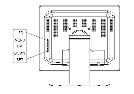
- Access Bigtide screen manager on monitor display by pressing Menu control button on monitor rear panel. See Figure 13.note: On-Screen Manager detail can be found here Bigtide HL1916 Screen Manager Controls.
Figure 13. Bigtide HL1916 LCD Monitor Control Button
- Due to the fact that Screen Managers can be accessed by anyone, custom setting can be altered. To assure correct baseline settings, first reset monitor back to OEM presets. Navigating to Menu Tools on the On-Screen Manager Main Menu and press Enter. Select Reset from the Others Menu using the Left/Right arrow buttons and press Enter. Then select Reset on the Reset Menu using the Left/Right arrow buttons and press Enter. All settings will be return to OEM presets.
2.3 EIZO S1921-X / S1923–H LCD Monitor, EIZO Screen Manager Setup
Procedure
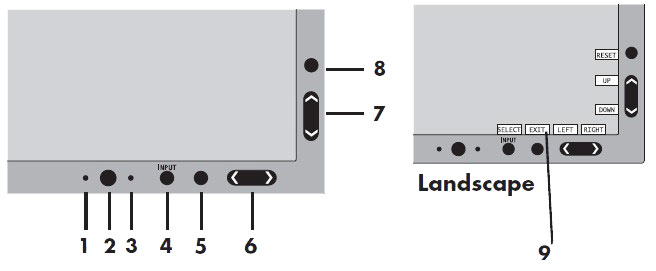
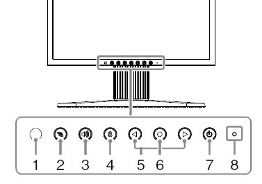
- Access EIZO Screen Manager on monitor display by pressing Enter control button on monitor front panel. See Figure 14.note:
On-Screen Manager detail can be found here EIZO S1921-X / S1923–H Screen Manager Controls .
Figure 14. EIZO S1921-X / S1923–H LCD Monitor Control Buttons
- Due to the fact that Screen Managers can be accessed by anyone, custom setting can be altered. To assure correct baseline settings, first reset monitor back to OEM presets. Navigating to Others on the Adjustment Menu using the Left/Right arrow buttons and press Enter. Select Reset from the Others Menu using the Left/Right arrow buttons and press Enter. Then select Reset on the Reset Menu using the Left/Right arrow buttons and press Enter. All settings will be return to OEM presets.
- Return to the Adjustment Menu by selecting Return using the Left/Right arrow buttons and pressing Enter as many times as appropriate to step back to main menu.
- Select Color Adjustment on the Adjustment Menu using the Left/Right arrow buttons and press Enter. Select Temperature using the Left/Right arrow buttons and press Enter. Then set color temperature to 6500K using the Left/Right arrow buttons and press Enter.
- Exit the Screen Manager menu by pressing Left/Right arrow buttons to select the Return and press Enter as many times as appropriate to step back to main
menu. Select Exit from the Adjustment
Menu to exit the Screen Manager.note: Exit the Screen Manager menu may also be accomplished by pressing Enter button twice quickly.
- Disable the Auto EcoView Feature on this monitor. Press the EcoView button to display the EcoView Menu. Use the Left/Right arrow buttons to select Auto EcoView Off and press Enter.
- Press the EcoView button again to turn
off the EcoView Menu display.note: If customer needs to set DICOM, press Enter button to enter ScreenManager, select Color → Color Mode → DICOM.
2.4 HP E190i LCD Monitor, HP Screen Manager Setup
Procedure
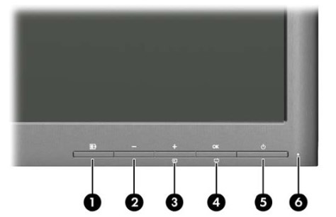
- Access HP LCD Screen Manager on monitor display by pressing Menu control button on monitor front panel. See Figure 15.note: On-Screen Manager detail can be found here LCD Video Monitor Setup DEL.
Figure 15. HP E190i LCD Monitor Control Buttons
3 Image Monitor Setup and Camera Calibration
The image monitor must be properly adjusted first before calibrating any camera filming devices. This procedure describes how to adjust the image monitor. Once the image monitor is adjusted, it is essential to re-calibrate the camera before the system is used for filming.
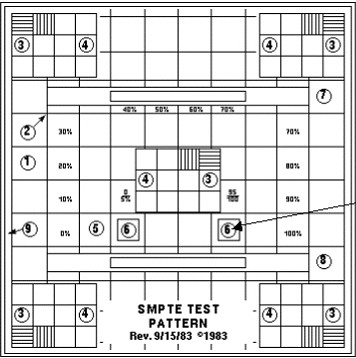
3.1 Installing the SMPTE Test Pattern
Figure 16. Sample Test Pattern
Procedure
- Access the Common Service Desktop (CSD).
- From the CSD select the Image Quality tab.
- From the menu select Install SMPTE pattern image. An Installation Window will appear.
- Allow the SMPTE pattern to load. A "Successful Copy" message
will appear when the load is complete.note: It can take as long as 10-12 minutes for the SMPTE pattern to load. Load progress shows up as successive dots in the Installation Window.
- Press Enter to leave the Installation Window.
- Click the Image Works icon, and select the Image Browser.
- Use the scroll bar, as required, to select the SMPTE test image from the Exam list.
- Click Full Viewer. If necessary, use the FORMAT option to select Full Screen mode.
- Leave the SMPTE test pattern on the image monitor.
3.2 Window and Level Settings
Procedure
- Set the default Window Setting to 100.
- With the cursor inside the SMPTE image displayed, hold down the middle mouse button and move the mouse in the horizontal plane. View the window control value at the base of the image and set the window control value to 100.
- Set the default Level Setting to 1024.
- With the cursor inside the SMPTE image displayed, hold down the middle mouse button and move the mouse in the vertical plane. View the level control value at the base of the image and set level control value to 1024.
- Inspect the SMPTE image displayed. The image should display all shades or the gray-scale. Fine adjust image brightness and contrast on monitor as necessary.
- Remove the SMPTE Pattern by selecting a different Exam from
the browser, or by selecting ESC on the keyboard.note: Because Operators are able to adjust Brightness and Contrast, they should be made aware of the impact on display image quality of doing so. If an Operator chooses to deviate from the above setups, the look of the camera film may be impacted as well. With the Image Monitor adjusted to properly display the SMPTE image, Film Camera Option Calibration may be completed if so equipped.
4 Display Monitor Positioning
4.1 Raise and Lower Monitor Screen
Procedure
- Place your hands on the side of the monitor.
- Lift or lower the monitor to the desired height.
Figure 17. Raise or Lower LCD Monitor Screen
4.2 Tilt and Swivel
Procedure
- Grasp both sides of the monitor screen with your hands.
- Adjust the monitor tilt and swivel as desired.
Figure 18. LCD Monitor Tilt and Swivel