- Topic ID: id_15460347
- Version: 2.0
- Date: Nov 8, 2018 1:39:34 AM
Inverter/Tank AC Wire Routing
Prerequisites
Overview
This procedure routes the HV cables from the JEDI inverter to the tank in such a way that the noise induced on the DAS cable is minimized and passes IQ tests. Procedure summary
-
Remove EMC box cover
-
Route cables according to graphics
Procedure
 warning
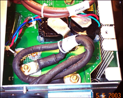
- Route and connect the HV cables in the inverter as shown below.
Figure 1. HV Cable routing and connections in the Inverter
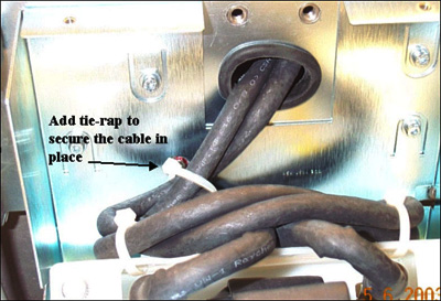
- Add tie-wrap to secure the cable in place. Both of the cables
should be routed in parallel and have one turn per every 6 inches
of wire.
Figure 2. Tie-wrapping the HV cables in place
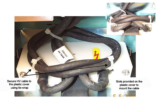
- Secure the HV cable to the plastic cover using tie wrap as shown
in Figure 3. Slots are provided on the plastic cover to mount
the cable.
Figure 3. Securing the HV cable to the plastic cover
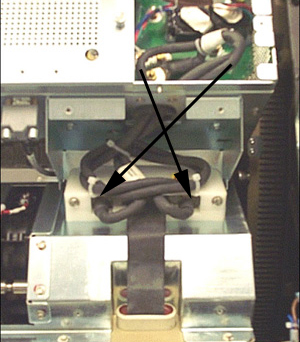
- Verify the cabling is correct as shown below. Proper routing
will connect the wiring as shown by the arrows in Figure 4.note:
Reversing this connection will not harm the system, as long as the system passes the appropriate retest steps in Finalization.
Figure 4. Correct cable routing
 |
Finalization
- No Finalization.