- Topic ID: id_15460404
- Version: 4.0
- Date: Jan 20, 2020 8:32:24 PM
Inverter Assy Replacement
Prerequisites
Overview
Procedure
- Raise the Table to maximum height.
- Move the Cradle and IMS to OUT limit position.
- Remove power from Table by turning off 120VAC, Axial Drive and HVDC switches on Service Switch Panel.
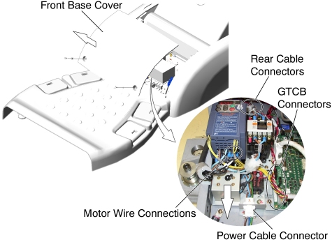
- Remove the Front Base Cover.
- Cut any tie-wraps, and disconnect motor wires (U, V, W) from the front of the Inverter Assy.
- Disconnect the following cable connectors:
-
Power Cable Connector
-
J1 - on the GTCB Assy
-
J2 - on the GTCB Assy
-
J100 - behind the Inverter Assy
-
J101 - behind the Inverter Assy
-
J102 - behind the Inverter Assy
-
- Loosen a screw, and slide the Inverter Assy toward the Gantry,
then remove it from the Table.
Figure 1. Inverter Assy Removal
- Install the new Inverter Assy in place, and tighten the screw.
- Re-connect all wires and cable connectors, and fix the cables using tie-wraps.
Finalization
- Re-install the Table covers.
- Power up the Table from the Service Switch Panel.
- Verify that the Table Up/Down function is operating normally.