- Topic ID: id_15460641
- Version: 2.0
- Date: Nov 8, 2018 1:36:21 AM
Install Gantry Alignment Laser and Bracket
Prerequisites
1 Gantry Alignment Laser
Procedure
- notice
- Rotate the gantry by hand until the collimator face plate is
at the 5 o’clock position.note:
With power OFF, the gantry movement is tight.
DO NOT pin the gantry during this alignment process.
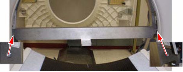
- With the top and back gantry covers removed, locate the two
M10 bolt holes as shown in Figure 1. These bolt holes are used to attach the laser
tool to the gantry.
-
The bolts can be installed using an 8 mm Allen wrench. Be careful not to bump the alignment light; the mounting space is tight near the alignment light. Tighten bolts until both are snug.
-
Do not drop bolts or the bar on the collimator faceplate. Attach the bar as shown in Figure 1.
-
Using a minimum 223 mm (9 in.) level placed on the attached bar, level the bar by rotating the gantry.
Figure 1. Alignment Bar Installation Location
-
 caution
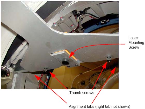
- Attach the laser centering plate onto the laser mounting bar
as shown in Figure 2. The plate is attached from under the alignment bar using two fixed
locators and two thumb screws.
Figure 2. Attach Laser Center Plate
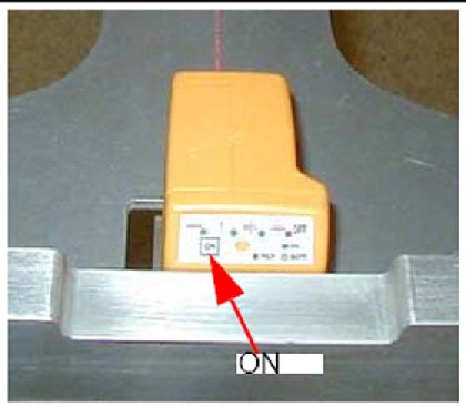
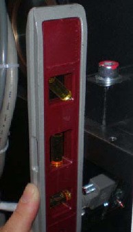
- When done, insert the laser and turn on the laser using the controls on the back. If the laser is loose when mounted, use a 2 in. piece of Velcro loop (fuzzy) section and attach it to the alignment plate over the attachment screw. Remount the laser and it should fit snugly without moving.
- When pressed, the ON button steps through
four different beam profiles and “Self-Leveling Off”.
Press the ON button until the “|”
beam shows. It is used for this operation.
Figure 3. Laser ON button
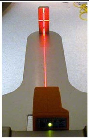
- Align the laser by carefully rotating the laser base assembly
so that the “I” beam shines through the center of the
alignment sight mounted on the end of the alignment plate.note:
The laser beam may be wider depending on the battery life.
- Use the locking screw on the bottom of the alignment bar to
secure the laser to the bar, as shown in Figure 4. When done,
the laser should fit snugly without moving on the mounting bracket.
Figure 4. Laser Centering
- caution
- After the laser is centered, notice that the laser beam also appears on the back wall. Place a piece of masking tape on the wall and carefully mark a line on the tape where the laser appears. This line is later used in the table alignment. This line is also useful in determining if the laser unit moves during the alignment process.
- Remove the alignment centering plate and store it in the alignment
case.
Figure 5. Table Center Line
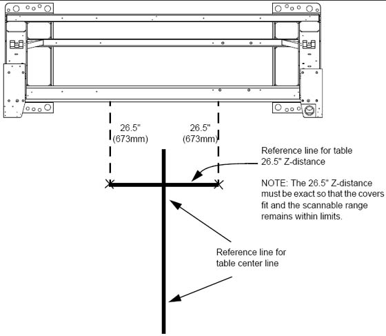
- Recheck the table-to-gantry reference line for 26.5 in. (± 0.25 in.) Z-distance. Refer to Figure 5.
- Turn off the laser but do not remove.
 |
 |
2 Install the Table Cradle Laser Alignment Plates
Procedure
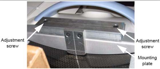
- Locate the aluminum accessory tray mounting plate with the three
holes on the rear of the cradle. Fit the rear alignment target into
the two mounting holes as shown in Figure 6. Use the adjustment
screw to adjust the fit as needed. When you are finished, the fit
should be snug, without play.
Figure 6. Cradle Rear Laser Alignment Tool
- Check that the table base is centered over the table center
line, and the base is on the 26.5 in.line (± 0.25 in.) made
on the floor.
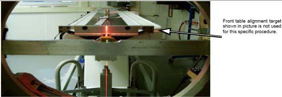
Figure 7. Rear Laser Alignment Tool - Installed
- Lower the table to the floor using the dollies, making sure
to maintain the 26.5 in. (± 0.25 in.) distance.
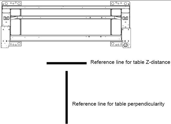
Figure 8. Two Reference Lines
3 Gantry Tilt Zero Alignment Check
Procedure
- Tools and Test Equipment: 9 inch level
- Procedure
-
Place the 9 in. level on the rear corner of the gantry as shown in Figure 9.
-
Check Gantry Alignment
Figure 9. 9 inch Level
-
Finalization
No finalization steps.