- Topic ID: id_15460402
- Version: 4.0
- Date: Jan 20, 2020 8:32:29 PM
IMS Encoder Spool Wire Replacement
Prerequisites
Overview
Procedure
- Raise the Table to maximum height.
- Move the Cradle and IMS to OUT limit position.
- Remove power from Table by turning off 120VAC, Axial Drive and HVDC switches on Service Switch Panel.
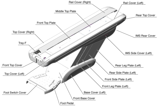
- Remove the following Table component and covers:
-
Cradle
-
Top Cover (Right/Left)
-
Rail Cover (Right/Left)
-
Top Plate (Front/Middle/Rear)
-
IMS Side Cover (Right/Left)
-
IMS Rear Cover
-
Front/Rear Side Plate (Left)
-
Front/Rear Leg Plate (Left)
Figure 1. Table Covers
-
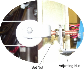
- Loosen the adjusting nut, to remove tension from the IMS wire.
Figure 2. Tension Adjuster
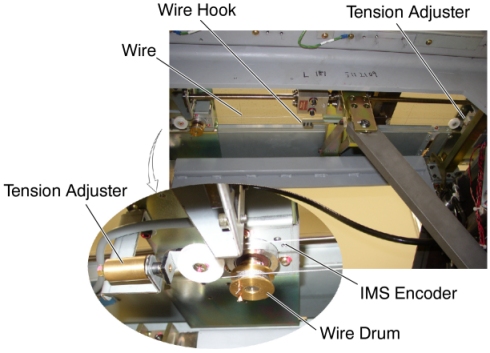
- Remove the IMS wire from the wire hook.
Figure 3. Spool Wire Location
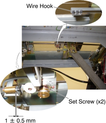
- Loosen 2 set screws on the wire drum, and remove the wire drum
from the IMS encoder, then remove the IMS wire assy from the Table.
Figure 4. Spool Wire Removal
- Install the new IMS wire assy :
- Attach the wire drum to the IMS encoder, and tighten the 2 set screws, to fasten the wire drum.
- Route the IMS wire as shown in Figure 4.
- Set the IMS wire to the wire hook as shown in Figure 4.
- Take off the adhesive tape from the wire drum.
- Rotate the adjusting nut in the CW direction until the distance D is approximately 1 ± 0.5 mm.
- Move the IMS manually IN and OUT, and verify that IMS movement is smooth.
Finalization
- Power up the Table from the Service Switch Panel.
- Perform IMS Characterization.
- Move the cradle and IMS IN and OUT completely 10 cycles and verify that Table movement is operating normally.
- Turn off all 3 switches (Axial Drive, HVDC, 120VAC), and re-install the Table covers.