- Topic ID: id_15460401
- Version: 4.0
- Date: Jan 20, 2020 8:32:06 PM
IMS Drive Belt Replacement
Prerequisites
Overview
Procedure
- Raise the Table to maximum height.
- Move the Cradle and IMS to OUT limit position.
- Remove power from Table by turning off 120VAC, Axial Drive and HVDC switches on Service Switch Panel.
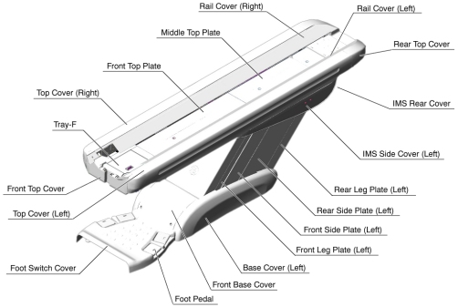
- Remove the following Table covers:
-
Top Cover (Right/Left)
-
IMS Rear Cover
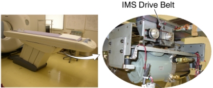
Figure 1. Table Covers
-
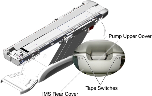
- Disconnect the cable connector of the tape switch.
Figure 2. Pump Upper Cover Removal
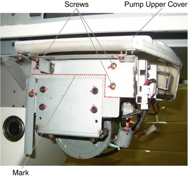
- Remove the pump upper cover as follows:
- To make re-installation easier, mark the position of pump upper cover on both sides by outlining the edge with a maker or pencil.
- Disconnect the cable connectors of the tape switches and touch sensors.
- Remove six (6) screws holding the both sides of the pump upper cover, and remove it.
Figure 3. Pump Upper Cover Removal
- Remove IMS motor cover.
Figure 4. IMS Moto Cover
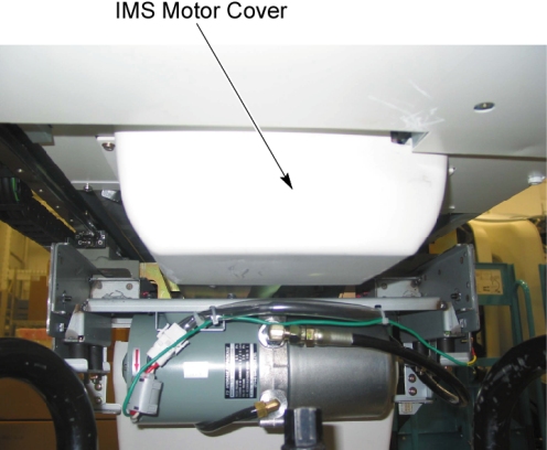
Figure 5. IMS Drive Belt Location
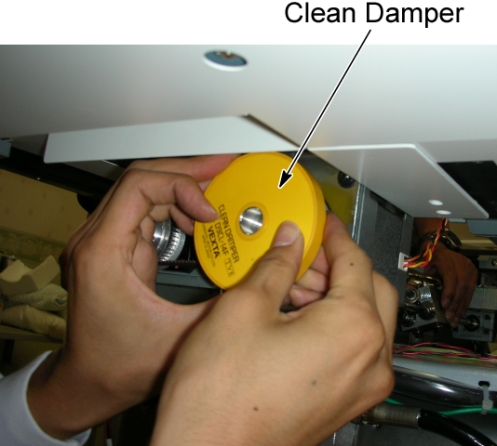
- If the clean damper is mounted on the IMS motor shaft, remove
it.
Figure 6. Clean Damper
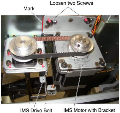
- Mark the motor bracket position for re-installation.
- Loosen 2 screws to remove tension from the belt, and remove
it.
Figure 7. IMS Drive Belt Removal
- Position the new belt on and around the motor pulley and the shaft pulley.
- Align the surface of the bracket with the mark, and tighten the 2 screws, to fasten the motor, with tension on the belt.
- Adjust the belt tension according to IMS Belt Tension Adjustment.
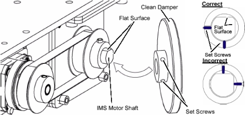
- If the clean damper is removed, re-install it to the IMS motor
shaft.
Figure 8. Clean Damper Installation
Finalization
- Power up the Table from the service Switch Panel.
- Use the Gantry control keys to move the IMS in and out.
When the Table functions properly, turn off all 3 switches (Axial Drive, HVDC, 120VAC), and re-install the Table covers.