- Topic ID: id_15460398
- Version: 4.0
- Date: Jan 20, 2020 8:32:29 PM
Hydraulic Return Hose Replacement
Prerequisites
Overview
Procedure
- Raise the Table to maximum height.
- Move the Cradle and IMS to OUT limit position.
- Remove power from Table by turning off 120VAC, Axial Drive and HVDC switches on Service Switch Panel.
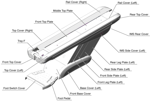
- Remove the following Table covers:
-
IMS Rear Cover
-
IMS Side Cover Right/Left)
-
Front/Rear Side Plate (Right/Left)
-
Front/Rear Leg Plate (Right/Left)
Figure 1. Table Covers
-
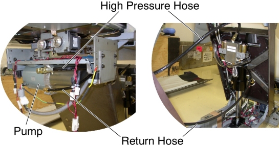
- Cut any tie-wraps holding the Return Hose.
- Disconnect the Return Hose from the hydraulic cylinder. A oil may spill out from the hose. Drain oil in the hose.
- Disconnect the Return Hose from the hydraulic pump.
Figure 2. Hydraulic Hoses
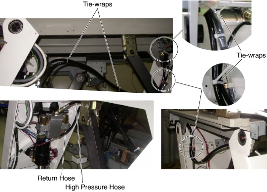
- Connect the new Return Hose, one end to the cylinder, and the
other end to the pump, then tie-wrap the hose in place.
Figure 3. Hydraulic Hoses Configuration
- Table pump lubrication:
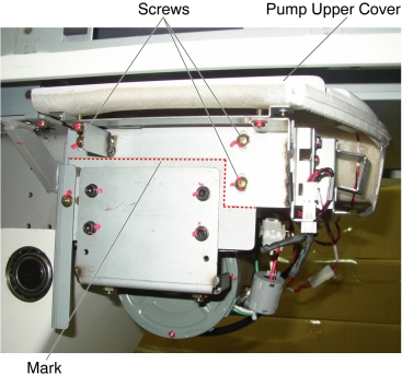
- Mark the position of pump upper cover on both sides for re-installation.
- Disconnect the cable connectors of the tape switches and touch sensors.
- Remove six (6) screws holding the both sides of the pump upper
cover, and remove the pump upper cover.
Figure 4. Pump Upper Cover Removal
- Pry a lid up using a flat-head screw driver.
Figure 5. Lid of Pump
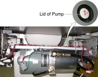
- Pour approximately 100cc of the oil into the pump.
- Power up the Table from the Gantry Service Switch.
- Raise the Table as high as possible.
- Turn off the Table from the Gantry Service Switch.
- Repeat step Step 9.d through Step 9.h until Table height reaches mechanical Up-limit.
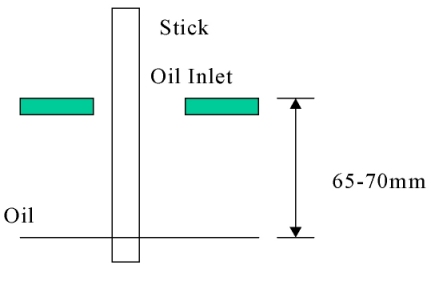
- Check the level of the oil by using a stick such as tie-wrap,
specification is shown in illustration below.
Figure 6. Check Oil Level
Finalization
- Secure any loose hoses with tie-wraps.
- Raise and lower the Table repeatedly to verify that the hoses do not catch or pull excessively.
- Turn off all 3 switches (Axial Drive, HVDC, 120VAC), and re-install the Table covers.