- Topic ID: id_15460608
- Version: 2.0
- Date: Nov 8, 2018 1:37:02 AM
High Voltage Tank Feedback Resistor Verification
Prerequisites
Overview
This document provides the necessary steps to verify the calibration of the Generator internal kV measurement system and the internal scan timer.
There are two methods for verifying the calibration of the Generator internal kV bleeder. The first, and recommended, method uses a digital multimeter as the readout instrument. The alternative uses an oscilloscope with a 10X probe.
1 Gantry Preparation
Procedure
- Move table to home position.
- Remove right side gantry cover.
- Turn off [HVDC ENABLE], [AXIAL DRIVE ENABLE] and [120 VAC ENABLE] switches on Service Switch panel.
- Remove scan window, gantry left side cover, gantry top covers
and gantry front cover.note:
Gantry front-cover control panels and display functionality are required during this procedure.
- Rotate gantry such that High Voltage Tank assembly is in 3 o'clock position.
- Engage rotational lock. See Equipment Service - Lockout-Tagout-PPE from Safety section.
- Insert lifting post into gantry frame and attach boom and hoist.
- Suspend High Voltage Bleeder from chain.
- Cut Ty-wraps on Inverter and Auxiliary Box clamps and remove High Voltage cable from clamps.
- Loosen High Voltage cable locking ring with spanner wrench.
- Remove High Voltage cable terminal stick from High Voltage Tank receptacle.
- With Dry Wipes, soak up oil in High Voltage Tank receptacle and in each High Voltage Bleeder receptacles.
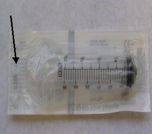
- Open syringe package from piston side (avoid any contact with
other tip).note:
Syringe should be unused and in original supplier package. Do not use a syringe in an open package; dirt collected on syringe can reduce oil quality and damage connector when operated.
note:Use only Mineral Based Transformer oil. Silicone based oil may damage High Voltage Tank and High Voltage Bleeder receptacles.
Figure 1. Syringe Package
- Fill up syringe with 18 ml oil from oil can.
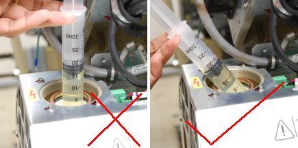
- Hold the syringe at an angle to the receptacle as shown in Figure 2 and pump 18 ml oil on to the receptacle wall.note:
DO NOT use the syringe in vertical position, this will result in air bubbles which increase the chances of high voltage breakdown.
Figure 2. Filling High Voltage Tank Receptacle
- Repeat steps 14 and 15 for each High Voltage Bleeder receptacles.
- Discard the syringe properly.note:
DO NOT REUSE THE SYRINGE.
- Install High Voltage Bleeder between X-ray Tube and High Voltage
Tank. (See Figure 3 or Figure 4)note:
Ensure ground cable between High Voltage Bleeder and High Voltage Tank is properly attached. Incorrect High Voltage Bleeder setup can result in damage to High Voltage Subsystem.
note:Ensure that each cable terminal stick key is lined up with receptacle key slot and terminal stick seats in receptacle properly.
Figure 3. High Voltage Bleeder (2375192) Connection Block Diagram
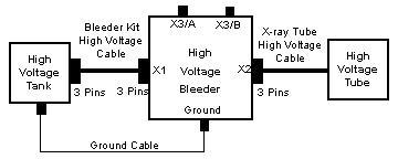
Figure 4. High Voltage Bleeder (2375192-2) Connection Block Diagram

- Turn on 120 VAC ENABLE switch on Service Switch panel.
- Press ESTOP RESET on Service Switch panel and wait until scan hardware is successfully reset.
2 Generator Internal kV Bleeder Test
2.1 Digital Multimeter Method - Recommended
Procedure
- Attach Banana-to-BNC Connectors to both ends of RG-58 Cable.
- Plug one RG-58 Banana-to-BNC connector into High Voltage Bleeder's
X3/A and X3/B plugs.note:
Ensure the polarity is correct (Banana plug Common Pin to High Voltage Bleeder X3/B).
- Plug other RG-58 Banana plug connector into Digital Multimeter
Volts and Common receptacles.note:
Ensure the polarity is correct (Banana plug Common Pin to Digital Multimeter Common).
- Turn on HVDC ENABLE switch on Service Switch panel.
- Turn on and configure Digital Multimeter.
- Set to VDC.
- Press RANGE button until display depicts 00.00.
- Set Digital Multimeter in a place where it can be easily viewed from console.
- Select DIAGNOSITCS from Service Desktop.
- Select KV & MA (X-RAY).
- In kV and mA Test (X-ray Functional Test) pane, set following parameter values.
- In Gantry Params pane, set following parameter
values.
- Click RUN.
- Press START on SCIM when it flashes and observe last stable volts reading just prior to turn off on Digital Multimeter.
- Obtain Measured kV value by ( -10kV/V ) * ( Digital Multimeter value).
- Record “Cathode/Total kV Average Value” from kV and mA X-ray tool.
- Verify that the following conditions are met:
- Measured kV is within 3% of kV Selection.
- “Cathode/Total kV Average Value” is within 2% of kV Selection.
-
Measured kV is within 2% of “Cathode/Total
kV Average Value”.note:
If any of these conditions are not met, replace High Voltage Tank and retest.
- Record results in appropriate GE e4879 Installation form, GE e4879 Certified Component Verification form, or GE Data Report Planned Maintenance Schedule form.
- In kV and mA Test (X-ray Functional Test) pane, set kV Selection to 100.
- Repeat Steps 10-15.
- In kV and mA Test (X-ray Functional Test) pane, set kV Selection to 120.
- Repeat Steps 10-15.
- In kV and mA Test (X-ray Functional Test) pane, set kV Selection to 140.
- Repeat Steps 10-15.
2.2 Oscilloscope Method - Alternate
Procedure
- Plug oscilloscope into one of the gantry's service outlets.
- Disconnect all probes from oscilloscope.
- Turn on oscilloscope and warm up for a minimum of 20 minutes.
- Perform oscilloscope Signal Path Compensation.note:
The menu selections are based on a TDS3034B oscilloscope and might be different on other oscilloscopes.
- Press UTILITY.
- Select CAL from SYSTEM.
- Press SIGNAL PATH PASS.
- Press OK COMPENSATE SIGNAL PATHS.note:
“Calibration in progress, please wait.” is displayed during compensation.
note:Compensation can take up to 10 minutes.
note:When completed, “Signal path compensation has successfully completed. Push MENU OFF to remove this message” is displayed.
- Press MENU OFF.
- Connect 10X probe to oscilloscope Channel 1 plug.
- Perform oscilloscope Probe Compensation.note:
Connectors and menu selection are based on a TDS3034B oscilloscope and might be different on other oscilloscopes.
- Attach probe tip and reference lead to PROBE COMP connectors.
- Press AUTOSET.
- Check shape of displayed waveform for a flat top square wave.note:
If waveform is not a flat top square wave, adjust probe Low Frequency Compensation and repeat (a) - (c).
- Attach Banana-to-BNC Connector to one end of RG-58 Cable.
- Plug Banana plugs into High Voltage Bleeder's X3/A and X3/B
plugs.note:
Ensure the polarity is correct (Banana plug Common Pin to High Voltage Bleeder X3/B).
- Attach Banana-to-Clips Connector to other end of RG-58 Cable.
- Connect oscilloscope 10X Probe Signal to red clip and oscilloscope 10X Probe Common to black clip.
- Turn on HVDC ENABLE switch on Service Switch panel.
- Configure oscilloscope.note:
The menu selections are based on a TDS3034B oscilloscope and might be different on other oscilloscopes.
- Set HorizontalSCALE to 200ms.
- Press CH 1.
- Set VerticalSCALE to 2 V / division.
- Set VerticalPOSITION to 2 minor ticks (0.4 of a division) from top of screen.
- Press TriggerMENU, SOURCE, CH. 1.
- Press TriggerMENU, COUPLING, DC.
- Press TriggerMENU, SLOPE, NEG.
- Set TriggerMENU, LEVEL to –3.00V.
- Press TriggerMENU, MODE & HOLD, NORMAL.
- Set HorizontalDELAY to OFF state.note:
This sets Horizontal Trigger to 10%.
- Press MEASURE, GATING, BETWEEN V BAR CURSORS.
- Press MEASURE, SELECT MEASUREMENT
FOR CH. 1, MEAN.note:
The MEAN is a weighted average function.
- Press MENU OFF.note:
Pulse mean is displayed on right hand side of screen.
- Perform oscilloscope Offset Value.note:
This is oscilloscope-offset value that will be subtracted from true measurement values in later steps.
note:Do NOT change the vertical scale on oscilloscope after measuring offset value.
note:The menu selection is based on a TDS3034B oscilloscope and might be different on other oscilloscopes.
- Press TriggerFORCE TRIG.
- Record oscilloscope Channel 1 mean value in volts.
- Select DIAGNOSTICS from Service Desktop.
- Select KV & MA (X-RAY).
- In kV and mA Test (X-ray Functional Test) pane, set following parameter values.
- In Gantry Params pane, set following parameter
values.
- Click RUN.
- Press START on SCIM when it flashes.
- Record “Cathode/Total kV Average Value” from kV and mA X-ray tool.
- On oscilloscope, use SELECT - COARSE knob to place left cursor to just inside of waveform front edge.
- Press SELECT and use SELECT
- COARSE knob to place right cursor to just inside of
waveform back edge.note:
Most of the pulse flat top should be between the two cursors.
- Record Channel 1 mean value in volts, including minus sign if there is one.
- Obtain Measured kV value by (-10kV/V) * (Channel 1 Mean value - Oscilloscope Offset value).
- Verify that following conditions are met:
- Measured kV is within 3% of kV Selection.
- “Cathode/Total kV Average Value” is within 2% of kV Selection.
-
Measured kV is within 2% of “Cathode/Total
kV Average Value”.note:
If any of these conditions are not met, replace High Voltage Tank and retest.
- Record results in appropriate GE e4879 Installation form, GE e4879 Certified Component Verification form, or GE Data Report Planned Maintenance Schedule form.
- In kV and mA Test (X-ray Functional Test) pane, set kV Selection to 100.
- Repeat steps 18-26.
- In kV and mA Test (X-ray Functional Test) pane, set kV Selection to 120.
- Repeat steps 18-26.
- In kV and mA Test (X-ray Functional Test) pane, set kV Selection to 140.
- Repeat steps 18-26.
3 Generator Internal Scan Timer
Procedure
- If Section 4.2.1 was performed, complete the following steps:
- Turn off HVDC ENABLE switch on Service Switch panel.
- Plug oscilloscope into one of the gantry's service outlets.
- Turn on oscilloscope and connect 10X probe to oscilloscope Channel 1.
- Perform oscilloscope Probe Compensation per Section 4.2.2 Step 6.
- Detach Banana-to-BNC Connector (one connected to Digital Multimeter) from RG-58 Cable.
- Attach Clips-to-BNC Connector to open end of RG-58 Cable.
- Connect oscilloscope 10X Probe Signal to red clip and oscilloscope 10X Probe Common to black clip.
- Turn on HVDC ENABLE switch on Service Switch panel.
- Configure oscilloscope per Section 4.2.2 Step 12.
- In kV and mA Test (X-ray Functional Test) pane, set following parameter values.
- In Gantry Params pane, set following parameter
values.
- Click RUN.
- Press START on SCIM when it flashes.
- On oscilloscope, adjust Select - Coarse knob to place cursor to just right of waveform left edge.
- Press SELECT and adjust Select
- Coarse knob to place cursor to just left of waveform
right edge.note:
Most of the pulse flat top should be between the two cursors.
- Record Measured Scan Time value in seconds as the time between the two cursors.
- Verify that Measured Scan Time is within 4% of Exp Time (sec).
- Record results in appropriate GE e4879 Installation form, GE e4879 Certified Component Verification form, or GE Data Report Planned Maintenance Schedule form.
- Click DISMISS.
4 Finalization
Procedure
- Turn off HVDC ENABLE switch on Service Switch Panel.
- Disconnect oscilloscope from High Voltage Bleeder.
- Turn off and unplug oscilloscope. Prepare for storage.
- Turn off 120 VAC ENABLE switch on Service Switch panel.
- Disconnect the High Voltage Bleeder from system and prepare bleeder components for storage.
- Perform Securing HV Cable.
- Install gantry front cover, gantry top covers, and gantry left side cover.
- Install scan window.
- Turn on 120 VAC ENABLE, AXIAL DRIVE ENABLE and HVDC ENABLE switches on Service Switch panel.
- Press ESTOP RESET on Service Switch panel and wait until scan hardware is reset.
- Install gantry right side cover.
- Store data form with system history records.