- Topic ID: id_15460690
- Version: 2.0
- Date: Nov 8, 2018 1:38:28 AM
Heat Exchanger Power Supply Replacement
Prerequisites
Overview
This procedure describes the steps necessary to install a heat exchanger power supply assembly onto the VCT gantry.
1 Preparation for Replacement
Procedure
- notice
- Remove gantry right side cover and disable Axial drive, HVDC
and 120VAC service switches from the service switch panel.
Refer to Replacement > Gantry > Enclosure > Cover Removal Procedures.
- Remove the gantry top and left side covers, scan window and front cover. Connect the cover E-stop circuit to the terminators on the gantry.
 |
2 Removal of old Power Supply Assembly
Procedure
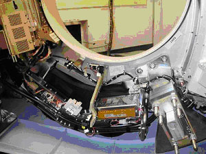
- Rotate the gantry so that the power supply is in the 6:00 position.
Refer to Figure 1.
Figure 1. Gantry Position
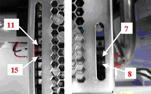
- Loosen inner screws on the right side wires of power supply;
insert a flat head screwdriver down through the top slot and remove
wires from the assembly. Refer to Figure 2. Take care
not to completely remove the screws.
Figure 2. Power Supply Wires
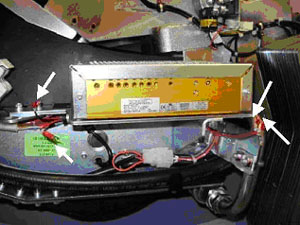 note:
note:To remove left side cables, slide power supply to the right to access with a screwdriver.
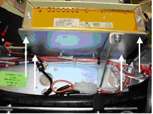
- Remove the four (4) screws on the bottom of the power supply
with a 3mm hex wrench. Refer to Figure 3
Figure 3. Mounting points of Power Supply
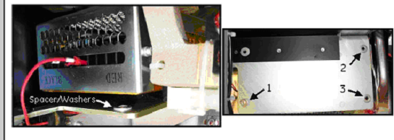
 note:
note:Use care when removing the 4 mounting Screws. See Illustration below: Spacer washers are located under the power supply typically only three corners require this spacer/washer. Save the washers for reinstall.
Figure 4. Spacers
- Slide power supply to the right side to access the left side wires and remove using the same method as the right side wires. Refer to Figure 2 and the corresponding note for details.
3 Installation of new Power Supply Assembly
Procedure
- Set new power supply on bracket and slide to the right so that the left side cable connections can be accessed with a screwdriver. Connect the left side wires by inserting cables into the power supply between the head of the screw and the board. Tighten the screw using a flat head screwdriver. Refer toFigure 5 (left) for wire position.
 warning
- Slide power supply into correct position and bolt onto the gantry
at the same four (4) points as the old supply. Refer to Figure 3. Torque front
two (2) bolts according to Table 6. Reinstall spacer/washer if removed earlier.
The two (2) back bolts are hard to get to if you do not have the recommended tools, 6 in. long 3mm ball hex bit and 6 in. long 1/4 in. hex drive. Either of the following 2 steps can be used to tighten these two (2) screws.
-
Preferred Method: Using a 3mm (6 in. long) hex bit and 1/4 in. (6 in. long) hex drive, torque according to Table 6.
-
Alternative Method: Using a 3mm hex wrench, seat the screws then continue to turn 1/4 turn to apply sufficient torque. Do not over tighten. Use approximate force applied to torque the other two (2) screws as a guide to the force limit for these two (2) screws. If either screw strips out, you will need to order a new supply. Do not allow operation of the system with stripped mounting screws.
note:Do NOT use this alternate torque method anywhere else in the system unless specifically defined by the service procedure.
-
- Use a screwdriver to reconnect the right side power supply wires
to the power supply. Refer to Figure 5.
Figure 5. Wire connections to power supply
4 Reassembly of Gantry
Procedure
- Install the gantry front cover, scan window, top and left side covers.
- Turn on the Axial drive, HVDC and 120VAC service switches from the service switch panel.
5 Finalization
Procedure
- Re-connect cables to the gantry display and controls panels.
- Replace gantry right side cover.
- Run the System Scanning Test.