- Topic ID: id_15460165
- Version: 3.0
- Date: Jun 15, 2020 11:02:44 PM
Heat Exchanger Fan Replacement
Prerequisites
Overview
This procedure defines the steps necessary to replace the heat exchanger fan.
Procedure
- Remove side, top, and front gantry covers.
- Turn OFF service switches on the Service Switch Panel (AXIAL DRIVE ENABLE, HVDC ENABLE, 120VAC).
- Rotate gantry so that Heat Exchanger is at the 2 o'clock position.
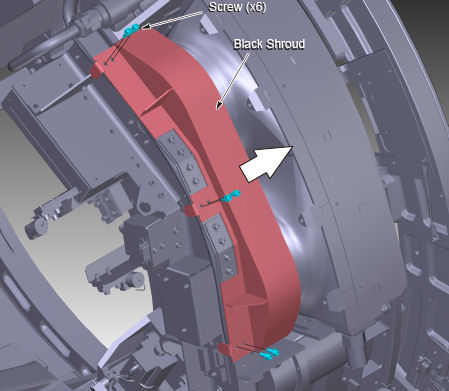
- Remove the Black Shroud by removing the 6 screws.
Figure 1. Black Shroud Removal
 note:
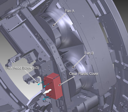
note:Power I/F board removal is not necessary, if the upper side of the fan (Fan A in Figure 2) is replaced.
- Remove the clear plastic cover by removing the three 3mm hex
head screws.
Figure 2. Clear Plastic Cover Removal
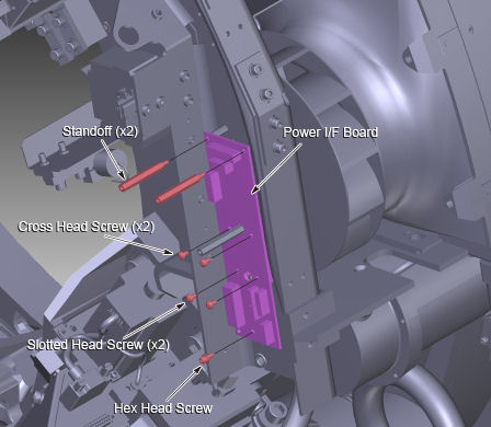
- Disconnect seven cable connectors from the power I/F board.
- Remove two standoffs, four screws and a hex head screw. And
remove the power I/F board.
Figure 3. Standoff, Nut and Screw Removal
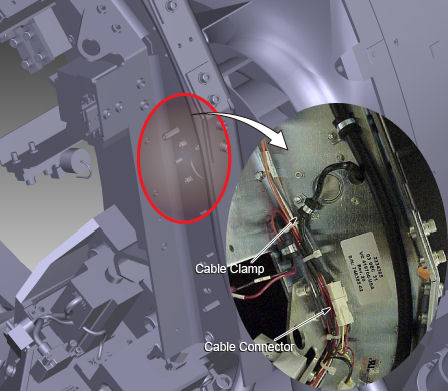
- Remove the screw and open the cable clamp, then disconnect the
cable connector of the fan.
Figure 4. Cable Clamp and Cable Connector
- Remove four hex head screws and remove the fan.
Figure 5. Fan Removal
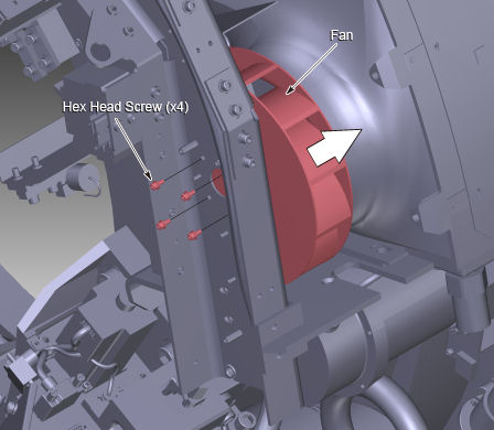
- Install the new fan into place, and tighten the 4 hex head screws (Torque: 2.0 Nm).
- Connect the cable connector of fan, and fix the cable with the cable clamp.
- Attach the power I/F board into place, and fix it using the two standoffs (Torque: 2.8 Nm), the four screws and the hex head screw (Torque: 3.3 Nm).
- Connect the seven cable connectors to the power I/F board.
- Attach the clear plastic cover into place, and fix it using the three hex head screws.
- Install the black shroud into place, and tighten the six screws (Torque: 3.3 Nm).
- Switch ON service switches on the Service Switch Panel (AXIAL DRIVE ENABLE, HVDC ENABLE, 120VAC). And confirm the replaced fan works properly.
- Install all covers on the gantry.
Finalization
- Perform System Scanning Test.