- Topic ID: id_15460437
- Version: 3.0
- Date: Jun 15, 2020 11:00:57 PM
HSDA PSU Replacement
Prerequisites
Overview
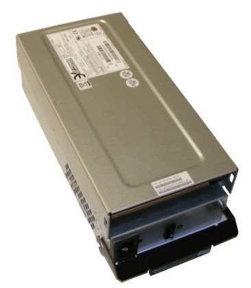
Figure 1. High Speed Disk Array (HSDA) Power Supply Unit (PSU) Module
1 Power-Off (Shut Down) the Console
Procedure
- Select one of the following methods to power off the Operator
Console:
-
If Applications are running, click the Shut Down icon and select Shut Down.
-
If Applications are down, open a Unix Shell using the Toolchest. Type: {ctuser@hostname} halt. Press Enter.
The Operator Console monitor will display a ‘System Halted’ message when it is acceptable to power off the Operator Console.
-
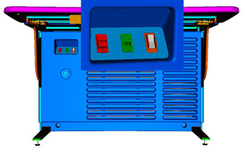
- Power OFF the Operator Console at the front panel switch. (See Figure 2.)
Figure 2. Console Power Switch
- Perform prescribed Lockout/Tagout procedure. For added protection, disconnect the Twist-N-Lock Main Power Cable from rear of console.
2 Remove Failed HSDA PSU Module
Procedure
- Remove the front and rear Operator Console Covers per prescribed cover removal procedure.
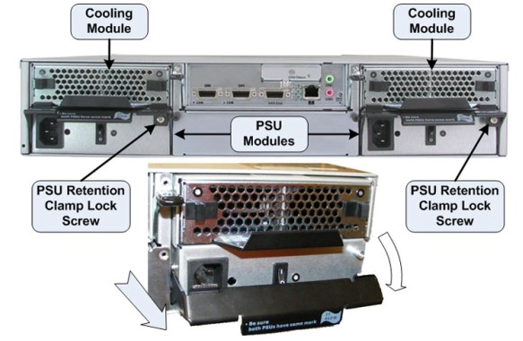
- At the rear of the Operator Console, disconnect the AC power Cord from the PSU Module being replaced.
- Remove the Phillips Retention Clamp Lock Screw and pull the
Retention Clamp down and away from the PSU Module to extract the module
from the HSDA Assembly.
Figure 3. HSDA PSU Module Removal
- Remove the PSU Module and set aside.
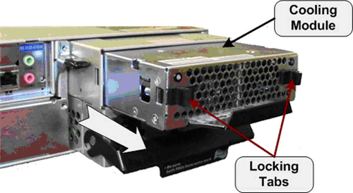
- Remove the Cooling Module from the PSU Module by retracting
the two (2) Locking Tabs on the Cooling Module then pull the module
free from the PSU Module.
Figure 4. HSDA Cooling Module Removal
3 Install Replacement HSDA PSU Module
Procedure
- Install the Cooling Module removed earlier into the replacement PSU Module. Check that the Cooling Module is fully seated in the replacement PSU Module and the Locking Tabs are engaged.
- Slide the replacement PSU Module into the HSDA Assembly PSU Module bay.
- Make sure the PSU Module is securely inserted, the Retention
Clamp is engaged and the Retention Clamp Locking Screw (Phillips)
is reinstalled.note:
IN ORDER TO MEET EMC REQUIREMENTS, THE CHASSIS MODULES MUST BE PROPERLY INSTALLED AFTER SERVICING. CHECK THAT THE MODULES ARE MOUNTED FIRMLY IN PLACE AND LOCKED DOWN WHERE APPLICABLE.
- Reconnect the AC Power Cord removed earlier and check that the PSU Module Power Switch is turned ON.
4 Power-On the Operator Console
Procedure
- Reconnect the Twist-N-Lock Main Power Cable from rear of console and remove Lockout Tagout protection applied earlier.
- Power ON the Operator Console at the console front panel switch.
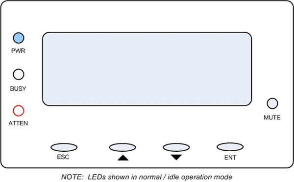
- Visually verify the HSDA Assembly LCD Panel Power LED is illuminated.
Figure 5. HSDA LCD Panel
5 Verify Replacement HSDA PSU Module Operation
Procedure
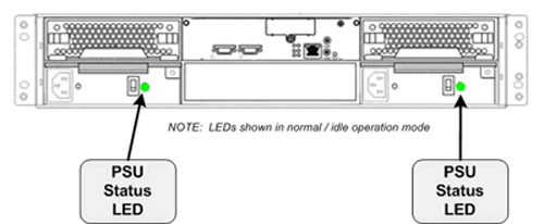
- Verify that the HSDA with replacement PSU Module has powered
up and is not displaying any Errors. The PSU Module Status LED located
close to the PSU Module Power Switch should illuminate Green.
Figure 6. HSDA PSU Status LED
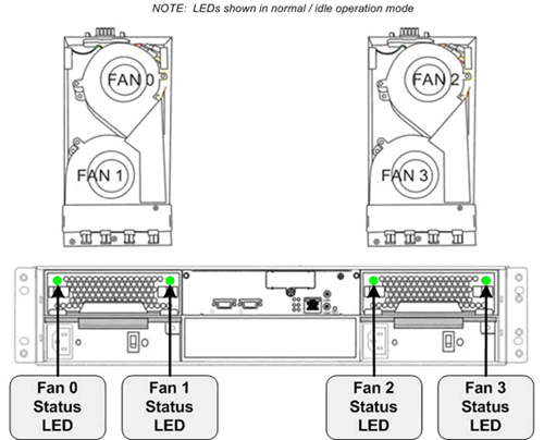
- Visually verify the HSDA Cooling Module Status LEDs are illuminated.
Figure 7. HSDA Cooling Module Status LEDs
 note:
note:See the HSDA Troubleshooting procedure if any errors appear.
6 Finalization
Procedure
- Refer to System Scanning Test to confirm proper operation.
- Reinstall Console Front and Rear Covers.