- Topic ID: id_15460139
- Version: 3.0
- Date: Jun 15, 2020 11:00:56 PM
HSDA Controller Module Replacement
Prerequisites
Overview
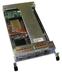
This procedure describes and illustrates the steps necessary to replace the High Speed Disk Array (HSDA) Controller Module (Figure 1).
Figure 1. High Speed Disk Array (HSDA) Controller Module
1 Power-Off (Shut Down) the Console
Procedure
- Select one of the following methods to power off the Operator
Console:
-
If Applications are running, click Shut Down and select Shut Down.
-
If Applications are down, open a Unix Shell using the Toolchest. Type: {ctuser@hostname} halt. Press Enter.
The Operator Console monitor will display a ‘System Halted’ message when it is acceptable to power off the Operator Console.
-
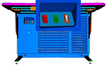
- Power OFF the Operator Console at the front panel switch.
Figure 2. Console Power Switch
- Perform the prescribed Lockout/Tagout procedure. For added protection, disconnect the Twist-N-Lock Main Power Cable from rear of console.
2 Remove Old HSDA Controller Module
Procedure
- Remove the Front and Rear Operator Console Covers per the prescribed cover removal procedure.
- At the rear of the Operator Console remove the SAS and Network Cables from the HSDA.
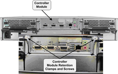
- Loosen and remove the two (2) Phillips screws holding the Controller
Module Retention Clamps in place.
Figure 3. HSDA Controller Module Mounting
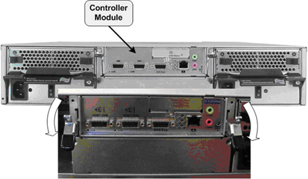
- Pull the two (2) Retention Clamps down and away from the Controller
Module to extract the module from the HSDA Assembly.
Figure 4. HSDA Controller Module Removal
- Carefully remove the Controller Module and set aside.
3 Install Replacement HSDA Controller Module
Procedure
- Slide the replacement Controller Module into the HSDA Assembly Controller Module bay.
- Make sure the Controller Module is securely inserted and replace
the two (2) Phillips screws in the Retention Clamps.note:
IN ORDER TO MEET EMC REQUIREMENTS, THE CHASSIS MODULES MUST BE PROPERLY INSTALLED AFTER SERVICING. CHECK THAT THE MODULES ARE MOUNTED FIRMLY IN PLACE AND LOCKED DOWN WHERE APPLICABLE.
- Reconnect the SAS and Network cables to the HSDA Controller
Module.
Figure 5. HSDA Controller Module Connections: HSDA 1 Connections
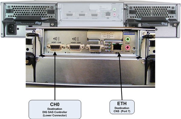
Figure 6. HSDA Controller Module Connections: HSDA 2 Connections (HD Only)

4 Power-On the Operator Console
Procedure
- Reconnect the Twist-N-Lock Main Power Cable from rear of console and remove Lockout/Tagout protection applied earlier.
- Power ON the Operator Console at the console front panel switch.
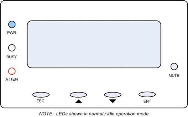
- Visually verify the HSDA Assembly LCD Panel Power LED is illuminated.
Figure 7. HSDA LCD Panel
- Do not allow Applications to start. During boot-up, cancel Application Startup when the CT Software Auto-start pop-up window appears.
5 Verify Replacement HSDA Controller Module Operation
Procedure
- Verify that the HSDA with replacement Controller Module has
powered up and is not displaying any Errors. note:
See HSDA Troubleshooting if any errors appear.
- In order to assure proper operation of the HSDA Assembly with its new Controller Module, perform the System Configuration procedure located in the applicable folder of this service methods publication.
- Do not allow Applications to start.
- During boot-up, cancel Application Startup when the CT Software Auto-start pop-up window appears.
- Open a Terminal window and log on as Root.
- Verify the parameter of HSDA Controller Module
-
Type: rsh darcEnter
-
Type: lsscsiEnter
The following one SCSI device is displayed. In this instance, proceed to step Step 3.d.
[0:0:0:0] disk IFT S12S-G1030 371E/dev/sda
If two SCSI devices are displayed as shown below, proceed to next sub step 3.c.iii.
[0:0:0:0] disk IFT S12S-G1030 371E/dev/sda
[0:0:1:0] disk IFT S12S-G1030 371E/dev/sda
-
Open Unix shell, then become “root”
-
Type java –jar /usr/g/scripts/raidcmd2.jar ENTER
-
Type connect darcarray ENTER
-
Type show host ENTER . Then, you can see below settings.
In-band External Interface: Enabled
Maximum Queued I/O Count: 1024
LUNs per Host SCSI ID: 4
Max Number of Concurrent Host-LUN Connection: 4
Number of Tags Reserved for each Host-LUN Connection: 4
Peripheral Device Type Parameters:
Peripheral Device Type: No Device Present (Type=0x7f)
Peripheral Device Qualifier: Connected
Device Supports Removable Media: Disabled
LUN Applicability: All Undefined LUNs
Cylinder / Head / Sector:
Cylinder: Variable
Head: Variable
Sector: Variable
If [Peripheral Device Type] is not No Device Present, please go to 3.c.vii to correct the setting.
-
Type set host dev-type=no-dev ENTER
-
To confirm setting, type show host ENTER. If it is not correct, repeat 3.c.vii.
-
Type reset controller ENTER.
-
System ask below question. Hence, please type y.
Are you sure to Reset Controller ? (y or n) : y.
-
Type Exit.
-
- Type: reconfigEnter
- On the System Tab, select Yes on the
Recreate Scan Disk Array and click Accept.note:
No other changes are required in the Preferences, Hardware, and Network settings. During the reconfiguration process the Scan Disk Array will be recreated. This will take approximately 20 minutes.
6 Finalization
Procedure
- After completing the System Configuration procedure, perform a complete shutdown of the Operator Console and restart the system.
- Perform System Scanning Test to confirm proper operation.
- Reinstall Console Front and Rear Covers.