- Topic ID: id_15460687
- Version: 3.0
- Date: Jun 15, 2020 11:00:55 PM
HSDA Chassis Replacement
Prerequisites
Overview
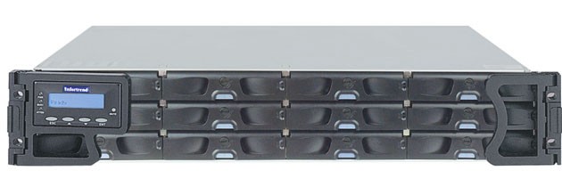
This procedure describes and illustrates the steps necessary to replace the High Speed Disk Array (HSDA) Chassis.
The FRU is a complete HSDA Chassis including the Controller, PSU and Cooling Modules. If needed, order the HSDA Hard Disk Drives separately.
Figure 1. High Speed Disk Array (HSDA) Chassis
1 Power-Off (Shut Down) the Console
Procedure
- Select one of the following methods to power off the Operator
Console:
-
If applications are running, click the Shut Down icon and select Shut Down.
-
If applications are down, open a Unix Shell using the Toolchest. Type: {ctuser@hostname} halt. Press Enter.
The Operator Console monitor will display a ‘System Halted’ message when it is acceptable to power off the Operator Console.
-
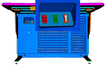
- Power OFF the Operator Console at the front panel switch. (See Figure 2.)
Figure 2. Console Power Switch
- Perform prescribed Lockout/Tagout procedure. For added protection, disconnect the Twist-N-Lock Main Power Cable from rear of console.
2 Remove Old HSDA Chassis
Procedure
- Remove the front and rear Operator Console Covers per prescribed cover removal procedure.
- Remove the cable connections at the rear of the HSDA chassis
being replaced. note:
Verify that all cables are labeled and clearly marked. If necessary, add a label for clarity.
- Remove the power two (2) cords from the PSU Modules at the rear of the HSDA chassis.
- Carefully remove the eight (8) Hard Disk Drive (HDD) Trays from
the HSDA chassis following the procedure below, needed to reduce weight
of assembly. (Place removed HDD Trays on a Static Mat while removed
from HSDA Chassis.)
- To remove an HDD Tray from the HSDA Assembly, unlock the HDD
Tray Door, press the HDD Tray Door Release Button, and pull up and
out on the HDD tray.
Figure 3. HDD Tray Release
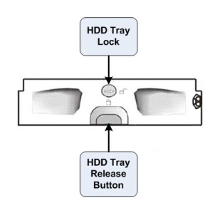
Figure 4. HDD Tray Removal
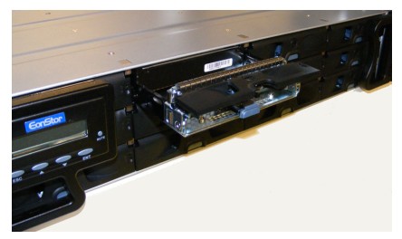
- Repeat of the other seven (7) HDD Trays in the top two (2) rows of the HSDA Assembly.
- To remove an HDD Tray from the HSDA Assembly, unlock the HDD
Tray Door, press the HDD Tray Door Release Button, and pull up and
out on the HDD tray.
- Remove the four (4) 5mm socket cap mounting screws from the
front of the HSDA chassis, holding the chassis to the Operator Console
rack.
Figure 5. HSDA Mounting
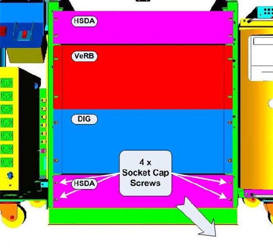
- Slide the HSDA chassis forward (out the front of console) and set aside.
3 Install Replacement HSDA Chassis
Procedure
- Slide the replacement HSDA Chassis into the Operator Console from the front.
- Replace the four (4) 5mm socket cap mounting screws to secure the HSDA Chassis to the Operator Console rack. Torque to 4.6 N-m.
- Mount the two (2) power cords to the rear of the HSDA Chassis and verify that its power supply switches are turned to the ON position.
- Replace the rear cable connection(s).
Figure 6. HSDA Assembly Connections & Destination: HSDA 1 Connections
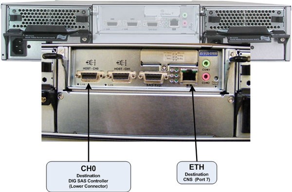
Figure 7. HSDA Assembly Connections & Destination: HSDA 2 Connections (HD Only)

- For cabling details, refer to the appropriate interconnect located in the System Diagrams folder of this service methods publication.
- Re-install all eight (8) HDD Trays back into the new HSDA Chassis, populating the top two (2) rows of the chassis.
- Make sure all HDD Trays are securely inserted and HDD Tray Doors
are closed and locked.
IN ORDER TO MEET EMC REQUIREMENTS, THE CHASSIS MODULES MUST BE PROPERLY INSTALLED AFTER SERVICING. CHECK THAT THE MODULES ARE MOUNTED FIRMLY IN PLACE AND LOCKED DOWN WHERE APPLICABLE.
4 Power-On the Operator Console
Procedure
- Reconnect the Twist-N-Lock Main Power Cable from rear of console and remove Lockout Tagout protection applied earlier.
- Power ON the Operator Console at the console front panel switch.
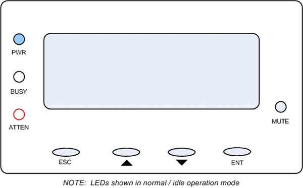
- Visually verify the HSDA Assembly LCD Panel Power LED is illuminated.
Figure 8. HSDA LCD Panel
- Do not allow Applications to start. During boot-up, cancel Application Startup when the CT Software Auto-start pop-up window appears.
5 Verify Replacement HSDA Chassis Operation
Procedure
- Verify that the HSDA Assembly has powered up and is not displaying
any Errors. note:
See HSDA Troubleshooting if any errors appear.
- In order to assure proper operation of the HSDA Assembly, perform the System Configuration procedure located in the applicable folder of this service methods publication.
- Do not allow Applications to start.
- During boot-up, cancel Application Startup when the CT Software Auto-start pop-up window appears.
- Open a Terminal window and log on as Root.
- Type: reconfigEnter
- On the System Tab, select Yes on Regenerate Scan Disk Array and click Accept.note:
No other changes are required in the Preferences, Hardware, and Network settings. During the reconfiguration process a new Array and Database will be created and the DHCP Server running on the Host Computer is reconfigured to support the new HSDA Ethernet MAC addresses. It is assumed that all previous patient data has been lost!
6 Finalization
Procedure
- After completing the System Configuration procedure, perform a complete shutdown of the Operator Console and restart the system.
- Refer to System Scanning Test to confirm proper operation.
- Reinstall Console Front and Rear Covers.