- Topic ID: id_15460463
- Version: 2.0
- Date: Nov 8, 2018 1:39:37 AM
HP xw8200 Memory Module Replacement
Prerequisites
Overview
This procedure describes the steps necessary to perform HP xw8200 Memory Module replacement. For preliminary requirements and finalization steps see HP xw8200 Lower Level FRU Replacement.
Memory Module Features:
-
8 memory slots for DIMMS
-
256-MB, 512-MB, 1-GB and 2-GB pairs
-
16 GB maximum configuration (4 GB maximum on Windows and 16 GB maximum on Linux)
-
Supports single-channel or dual-channel DIMMs
-
Supports DDR2-400
-
No support for mirroring, no spare DIMM support
-
Standard ECC (72-bit ECC)
-
Enhanced ECC (x4 SDDC or 144-bit ECC) in dual-channel mode when all DIMMs are x4
-
DED retry
1 Workstation Service Preparation
Perform the following steps before servicing the workstation.
Procedure
- Remove/disengage any security devices that prohibit opening the workstation.
- Disconnect all peripheral device cables from the workstation.
2 Memory Module Removal
Procedure
- Remove access panel cover per HP xw8200 Lower Level FRU Replacement.
- Lay the workstation on its side with the system board facing up.
- Gently push outwards on the socket levers on the slot that contains the suspected faulty memory module. (See Figure 2 for slot locations.)
- Lift the DIMM straight up and remove it from the unit (Figure 1).
Figure 1. Lift DIMM Straight Up
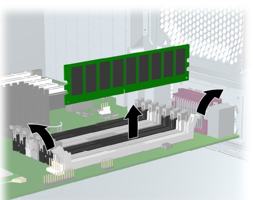 note:
note:DIMMs and the DIMM sockets are keyed for proper installation. Be sure these guides line up when installing a DIMM.
3 Memory Module Installation Considerations
To install a memory module, reverse the previous sequence and insert memory module in slot where faulty memory module was removed. Be aware of the following considerations:
-
Memory modules must be loaded in valid configurations.
-
DDR SDRAM is loaded as matched pairs. (For example, if you place a memory module of 1 GB in slot 1, you must also insert a 1-GB module in slot 2.)
-
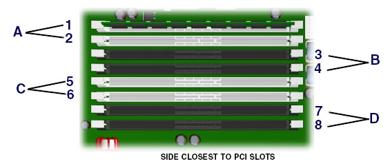
Memory modules are loaded in pairs in order of size, from smallest to largest, beginning with memory module pair A (closest to PCI slots). (For example, if you have 3.5 GB of memory composed of two 256-MB modules, two 512-MB modules and two 1-GB modules, load the 256-MB modules in memory module pair A, the 512-MB modules in pair B, and the 1-GB modules in memory module pair C.)
-
The DIMM is installed in socket 1 if only installing one DIMM.
-
The first matched DIMM pair is installed in socket set A.
-
Subsequent matched DIMM pairs are installed in sets B, then C, and lastly D (farthest from power supply). (See Figure 2.
Figure 2. Installing DIMM Pairs
 note:
note:The BIOS generates warnings/errors on invalid memory configurations.
-
In DDR2 mode, dual-rank DIMMs are placed farther from the Memory Controller Hub (MCH) than single-rank DIMMs.
-
If there is no way to obtain a valid memory configuration by disabling some of the plugged-in memory, the BIOS will halt with a diagnostics 2004 code for memory error (4 beeps/blinks).
-
If the BIOS can find a valid memory configuration by disabling some of the plugged-in memory, it will do so and will report a warning during POST (“215-mismatched memory”). The system can still be booted in this condition.
4 Finalization
No finalization steps.