- Topic ID: id_15460134
- Version: 3.0
- Date: Apr 9, 2020 8:48:29 PM
HP Host Computer Hard Drive Exchange
Prerequisites
Overview
This optional procedure is used when retaining the original hard drives in a failed HP Host Computer (xw8000 or xw8200). ALL drives must be swapped at once. The drives are not considered a FRU because they cannot be ordered separately from the HP Host Computer. A 4th disk drive (5111653) is available as a FRU for PET systems only.
This procedure only applies when swapping internal components between the same HP types. Swapping components between an HP xw8000, xw8200, or xw8400 is not allowed.
1 Remove the Side Cover
With ALL cables removed from the old and new Host Computers, perform the following steps:
Procedure
- Unlock the cover on the side of the old Host Computer. The cover keys are attached to the back panel of the system.
- Pull out on the side cover latch to release the side cover.
- Tilt the cover open, then lift it off. Refer to Figure 1.
Figure 1. Opening the Side Cover
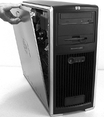
- Repeat the above procedure, to open the new Host Computer.
2 Remove the Hard Drives
Procedure
- Place the Host Computer on its side with the system board facing up.
- Label each SCSI connection as follows:
-
OS drive resides in slot 1 (bottom) -- label white SCSI connector tag as “Channel 1”.
-
Image disk 1 resides in slot 2 -- label white SCSI connector tag as “Channel 2”.
-
Image disk 2 resides in slot 3 -- label white SCSI connector tag as “Channel 2”.
-
(For PET Systems only) PET Image Database Drive resides in slot 4 (top-most) -- this 4th disk drive will be on SCSI Channel 2 as Image disk 1 and 2. It will no longer be connected to SCSI Channel 1.
note:You can also refer to Figure 5 for an example of how to connect the drives.
-
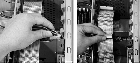
- Remove the power and SCSI data cables from each drive. Refer
to Figure 2.
Figure 2. Hard Drive Cables
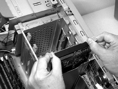
- Place your fingers on the colored release clips on the sides
of the drive, and squeeze inward. Pull gently just enough to release
the drive rail latches. Refer to Figure 3.
Figure 3. Hard Drive Rails
- notice
- Grasp the hard drive with your hand and pull out.
- Place the hard drive (with rails attached) on a static mat.
- notice
- Repeat the above procedures to extract all hard drives from the old (failed) Host Computer.
- Repeat the above procedures on the new Host Computer to extract all hard drives.
 |
|
3 Install the Hard Drives
Procedure
- notice
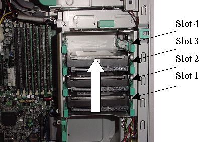
- Insert the site's original drives into the exact same slots
of the new Host Computer. PET systems without Dimension Console will
have a 4th drive, which must be placed in Slot 4. Load the drives
in the order shown in Figure 4.
Drive 1 (OS) should be installed first, Drive 2 (ID #1) next, then Drive 3 (ID #2). For PET systems without Dimension Console, insert Drive 4. Press down gently until each drive snaps into place.
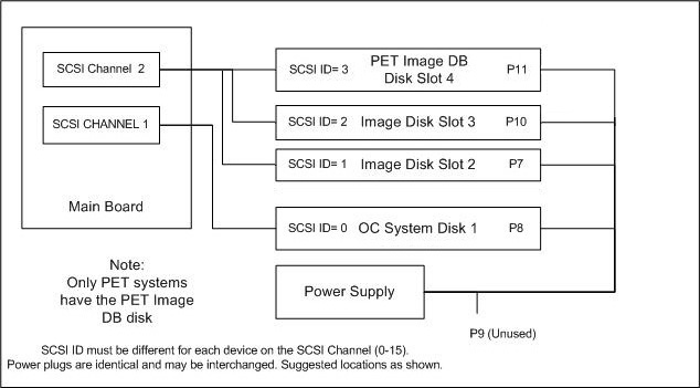
Figure 4. SCSI Drive Loading Order
-
Drive slot 1 is the bottom slot and must house the OC System Hard Drive (OS) and be connected to SCSI Ch1 and P8 power.
-
Drive slot 2 houses the Image Hard Drive #1 (ID #1) and must be connected to SCSI Ch2 and P7 power.
-
Drive slot 3 houses the Image Hard Drive #2 (ID #2) and must be connected to SCSI Ch2 and P10 power.
-
(For PET Systems only) Drive slot 4 is the PET Image Database Drive and must be connected to SCSI Ch2 and P11 power.
-
- Connect the drive cables:
- Connect the proper power cable to each hard drive (see Figure 5).
Figure 5. SCSI Drive Power Cable Connections
- Connect the proper SCSI Data cable to each hard drive. Label
as follows:
-
OS drive resides in slot 1 (bottom) -- label white SCSI connector tag as “B”.
-
Image disk 1 resides in slot 2 -- label white SCSI connector tag as “ID1”.
-
Image disk 2 resides in slot 3 -- label white SCSI connector tag as “ID2”.
-
(For PET Systems Only) PET Image Database Drive resides in slot 4 (top-most) -- label white SCSI connector tag as “P”.
-
- Do NOT change the jumper settings on any of your site's original drives.
- Connect the proper power cable to each hard drive (see Figure 5).
- Repeat the above procedures on the old (failed) Host Computer
to install all hard drives removed from the new Host Computer. note:
The old (failed) Host Computer must have the new drives installed when it is returned.
|
4 Replace the Side Cover
Procedure
- Ensure that all internal cables are properly connected and safely routed in the new Host Computer.
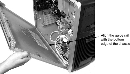
- Place the side cover onto the Host Computer chassis (aligning
the guide rail on the bottom inside edge of the cover with the bottom
edge of the Host Computer chassis). Refer to Figure 6.
Figure 6. Aligning and Closing the Cover
- Verify no cables are pinched, and gently close the cover.
- Lock the cover using the key provided.
- Repeat the above procedure, to close and lock the original Host Computer, with the new drives installed.
5 Finalization
A Reconfig is required when the console is powered on.
Procedure
- Continue with HP Host Computer Replacement (if applicable).