- Topic ID: id_15460195
- Version: 2.0
- Date: Nov 8, 2018 1:38:24 AM
Gantry Top Covers & Fan Removal (Removable Fans)
Prerequisites
Overview
The Gantry Top Covers consist of a Right and Left Top Cover, and two fan assemblies. The Top Covers fasten to the front and rear covers, and the fan assembly fastens to the corresponding Top Cover. See Figure 3 for a sample configuration.
Procedure
 caution
- caution
- caution
- notice
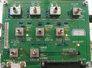
- Turn OFF the three (3) main power switches
(HVDC, 120VAC, and Axial Drive) on the Service Switch Panel (SSP).
See Figure 1.
Figure 1. Service Switch Panel
- Remove the Top Cover Fan Assemblies as follows:
- Reach beneath the Top Cover and unscrew the captive thumbscrews
(Release Screws) that fasten the Fan Assembly to the Top Cover.
Figure 2. Preparing to Remove the Gantry Fan Assembly
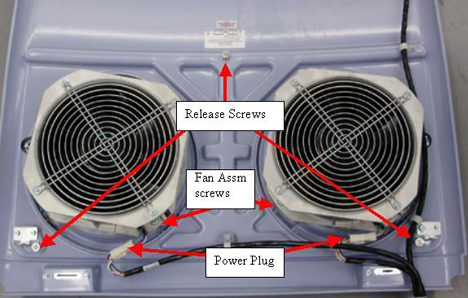
- On the Top Cover, disconnect the two power plugs (one to each fan).
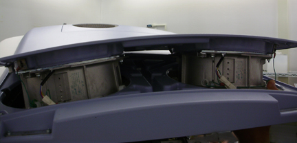
- Push up on the fans and grab the fan pan from the top to remove the Fan Assembly. See Figure 3.
Figure 3. Remove Gantry Fan Assembly
- Reach beneath the Top Cover and unscrew the captive thumbscrews
(Release Screws) that fasten the Fan Assembly to the Top Cover.
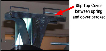
- With fan assembly removed, lift the end of the Top Cover nearest
to the side cover then tilt upwards and slide the cover down about
75 millimeters, to disengage the cover tab from the mounting bracket.
See Figure 4.
Figure 4. Top Cover Tabs
- Lift the cover to clear the bracket and Gantry assemblies.
- Reinstall fans when needed by reversing this procedure.
 |
|
|
 |
Finalization
- Verify fan operation by watching fans right after power is restored. All fans should come on initially after gantry power is restored. After the power up sequence, firmware control takes over and may turn some fans off.
- Verify all covers, especially side covers are properly secured.
- Ensure there is no interference during all tilt range.