- Topic ID: id_15460411
- Version: 2.0
- Date: Nov 8, 2018 1:38:23 AM
Gantry Stationary (CFC) Fan Control Module Replacement
Prerequisites
Overview
This procedure defines the steps necessary to replace the stationary side Fan Control Module.
1 CFC Module Removal
Procedure
- Remove gantry right side cover.
Refer to
- Turn OFF the Axial Drive, HVDC and 120 VAC switches on the gantry’s Service Switch Panel.
- Remove the gantry left side cover, top covers and rear cover.note:
Service cannot be performed from the left side for rooms with limited access between left side and room wall.
- Perform all required LOTO activities to ensure no power to the gantry.
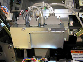
- The CFC module is located on the left side of the gantry between
the stationary 48VDC power supply and TGPU. See Figure 1.
Figure 1. CFC Module
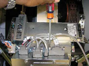
- The CFC module has 4 cables on the top. Disconnect all 4 cables
before removing the module. See Figure 2.
Figure 2. Disconnecting CFC Cables
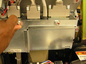
- Using the 2 thumbscrews, open the cover on the CFC module. See Figure 3.
Figure 3. CFC Module Cover
- Inside, remove the Molex connector from J2.
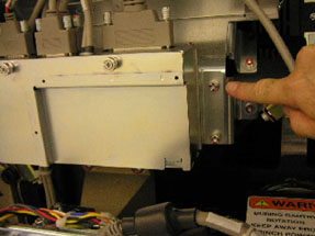
- The CFC module is secured to a gantry mounting plate with 6mm
hex-head screws on each side. Remove all screws with a 5 mm hex wrench.
See Figure 4.
Figure 4. CFC Mounting Plate
- Slide the module toward the back of the gantry to remove.
2 CFC Module Replacement
Procedure
- Install the new control module using the 6 mm (5 mm hex wrench) screws.
- Reconnect all cabling removed, reference section above.
- Install CFC front cover after installing the molex internal connection.
- Install the gantry rear cover and top covers.
Refer to
- Remove the LOTO and power up the system.
- Enable 120 VAC HVDC and Axial Drive service switches from the
service switch panel. Press the table drives enable button on the
lower right corner of the service switch panel.
Check to make sure all top cover fans come on right after gantry power up and that the gantry blower fan on the lower left comes on. Fans come on at 50% during hardware reset process.
- Install the gantry left and right side covers.
3 Finalization
Procedure
- Monitor the operator message area until the system indicates the detector temperature has returned to normal.
- Perform a Fastcal from the Daily Prep button on the Operator console.
- Perform a Quality Assurance Test from the Functional Checks menu of the service manual to ensure system operation.