- Topic ID: id_15460161
- Version: 3.0
- Date: Jun 15, 2020 11:02:42 PM
Gantry Rear Cover Removal and Re-Install
Prerequisites
Overview
This procedure explains how to remove and re-install the CT Gantry rear cover.
1 Removal
Procedure
- Assemble the rear cover dolly.
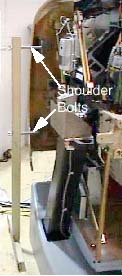
- Tighten the two (2) shoulder bolts to the rear cover.
Figure 1. One Side of the Rear Cover Dolly
 caution
- Fit side dolly through the shoulder bolts and secure assembly with two (2) wing nuts. See Figure 1
- Repeat steps a and b for the other side dolly.

- Tighten the two (2) shoulder bolts to the rear cover.
- danger
- notice
- Disconnect cables on the right side of the rear cover.
- Remove rear cover.
- Disengage upper and lower cantrell brackets on both sides of
the rear cover.
-
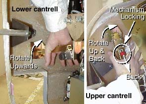
Using steady but firm pressure, lift each of the lower cantrell brackets from their associated retainers. See Figure 2.
Figure 2. Releasing cover brackets
-
Disengage the locking mechanism on the upper cantrell brackets by using your thumb to slide the trigger (red lever) back. This will release the locking mechanism and allow the cantrell to be rotated upwards with steady and firm pressure.
-
- Disengage the rubber retaining straps on both sides.
- Disengage the cam latch just above the rubber straps.
- Move cover away from gantry as needed.
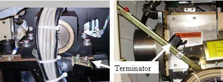
- To keep the E-Stop loop connected, connect cable J1 to the terminator
located on the cantrell arm or on the gantry frame below the cantrell.note:
There are 3 cables, each of which is unique. The ribbon cable is not used in the Service configuration. The other 2 cables will only fit in the terminator or the control panel, not both.
Figure 3. Terminator locations
- Disengage upper and lower cantrell brackets on both sides of
the rear cover.
 |
2 Installation
Procedure
- Position cover in back of gantry.
- Attach the rear cover
- Align the studs on both sides of the rear cover with the receivers located on the gantry frame.
- Insert the stud on one side into its associated receiver and
attach the rubber retaining straps. Then insert the stud on the other
side into its associated receiver and attach its rubber retaining
straps.note:
You may find it helpful to lift "up" on the cover to align the stud while attaching the rubber retaining straps.
- Engage the cam latch just above the rubber straps on the cover mount bracket.
- Reattach upper and lower cantrell brackets on both sides.
- Remove upper cantrell brackets from service position and rotate them into position over their associated retaining pins. Press down firmly on the bracket and snap it into place. The locking mechanism on each upper bracket should lock the bracket securely into place. Perform this action on both sides.
- Remove lower cantrell brackets from service position and rotate
them into position over their associated retaining pins. Press down
firmly on the bracket and snap it into place.note:
Adjustment of the cantrell brackets can cause misalignment of the top and side covers. The upper and lower cantrell brackets do not require adjust during normal use.
- Remove dolly, disassemble and store safely away.
- Reattach cables to cover.
3 Finalization
Procedure
- Continue with other cover installation procedures as necessary. When AC power is restored to the system, prior to enabling axial drive or HVDC, remember to rotate the gantry by hand to ensure there is no interference between covers and rotating components.
- When power is restored, Observe Gantry Display and Gantry Control panels during power on. Verify Power On Self Test (POST) completes normally and all cover indicators were illuminated during the POST. Verify that all Gantry control panels are functional with no ERR indicators. Also verify that the Gantry to Operator intercom is functional.
- Verify all covers, especially side covers are properly secured.
- Ensure there is no interference during all tilt range.