- Topic ID: id_15460445
- Version: 2.0
- Date: Nov 8, 2018 1:38:34 AM
Gantry GFI Replacement
Prerequisites
Overview
This procedure defines how to replace the Gantry GFI breaker.
Procedure
- Remove gantry right side cover.
Refer to
- notice
- Turn OFF the three (3) main power switches (HVDC, 120VAC, and Axial Drive) on the Service Switch Panel.
- Perform required LOTO procedures to lock out power at the A1 Panel.
- Remove the gantry top cover for easier access to the GFI breaker.
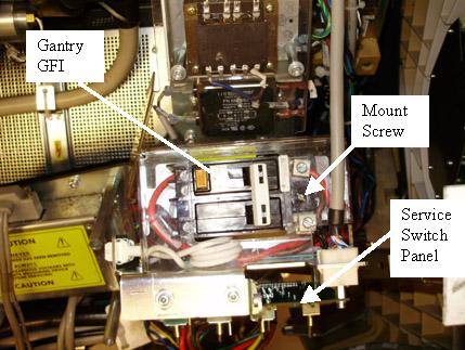
The gantry GFI circuit breaker is mounted on a panel directly behind
the service switch panel.
Figure 1. Gantry GFI Breaker - Top View
- Remove the plastic (or metal depending on system version) safety cover.
- Remove the wires from the load and input side of the GFI breaker. All leads are labeled, but do record wire locations.
- The breaker is mounted to the plate with a slot head screw on
one end and held in place by a bracket on the other end. Remove the
screw, tilt the GFI breaker up and pull towards rear cover to remove.
Figure 2. GFI Side View
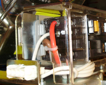
- Install new GFI by sliding the front end (front cover side) under bracket. See Figure 2.
- Screw the GFI breaker in place on the back end (rear cover side).
- Reconnect all power leads removed. Observe all lead labels and all should be securely tightened. See Figure 2 as a reference.
- Install plastic safety cover.
- Turn on the GFI breaker.
 |
Finalization
- Remove the A1 Lockout/Tagout. Power up the console.
- Install the gantry top cover.
Refer to
- Enable 120 VAC, HVDC and Axial Drive service switches from the service switch panel. Press the table drives enable button on the lower right corner of the service switch panel.
- Install the gantry right side cover.
- Perform a System Scanning Test from the Functional Checks menu of the service manual to ensure system operation.