- Topic ID: id_15460368
- Version: 2.0
- Date: Nov 8, 2018 1:38:20 AM
Gantry Cover Tilt Sensor Replacement
Prerequisites
Overview
This procedure defines the steps necessary to replace the Gantry front and rear cover tilt sensor replacement.
1 Preparation
Procedure
- Move Table to the home position.
- Remove gantry right side cover.
Refer to
- Turn OFF the Axial Drive, HVDC and 120 VAC switches on the gantry’s Service Switch Panel.
- Remove the gantry left side cover, top covers and front cover.
2 Front Cover tilt sensor
Procedure
- On the back of the front cover disconnect touch strip cable
from the tilt sensor.
Figure 1. Gantry Tilt Sensor on Front Cover
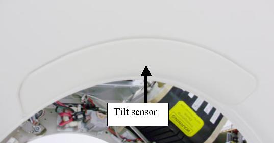
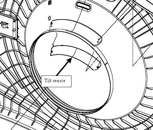
Figure 2. Front cover Tilt Sensor
- Remove 2 nuts (9/32 inch socket) that secure touch sensor pad to the front cover.
- Install new touch pad and tighten the 2 nuts to the following
values.
3 Rear Cover tilt sensor
Procedure
- On the back of the back cover disconnect touch strip cable from
the tilt sensor.
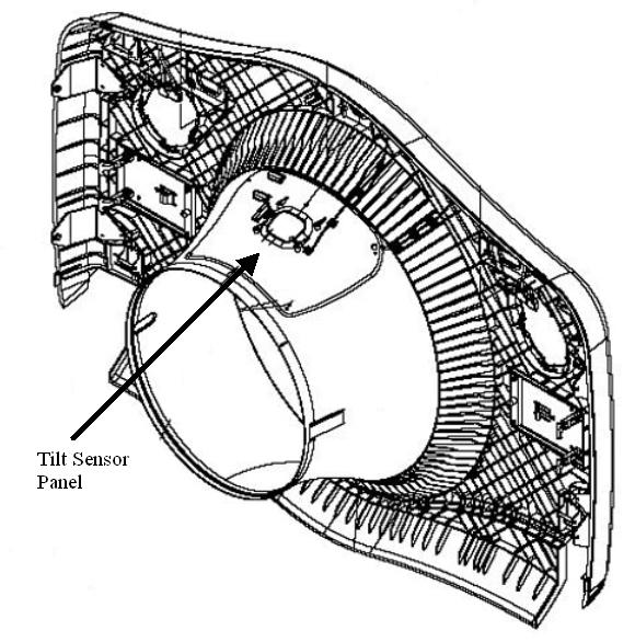
Figure 3. Rear Cover Tilt sensor
- Remove 4 nuts (9/32 inch socket) that secure touch sensor pad to the cover.
- Install new touch pad and tighten the 4 nuts to the following
values.
4 Gantry reassembly
Procedure
- Using an ohm meter, check the tilt sensor by connecting the ohm meter to the two lines from the sensor at the connector. The tilt sensor should read 20K ohms prior to pressing on the sensor and then approximately 20 ohms when the sensor is pressed. Check the torque on the nuts if this check fails.
- Reconnect the cable.
- Install the gantry front cover, top covers and left side cover.
Refer to
- Enable 120 VAC HVDC and Axial Drive service switches from the service switch panel. Press the table drives enable button on the lower right corner of the service switch panel.
- Install the gantry right side cover.
5 Finalization
Procedure
- From the front cover control panel, press and hold the gantry forward tilt button and then press on the tilt sensor while still tilting gantry. Verify the gantry tilt stops.