- Topic ID: id_15460450
- Version: 2.0
- Date: Nov 8, 2018 1:38:22 AM
Gantry Cooling Fan Replacement
Prerequisites
Overview
This document defines the fan replacement process for two types of top covers, one with fixed main fans and one with the main fans removable as a pair.
The top cover fans are controlled by the stationary CFC board. You can swap the fan connections to verify that the fan is defective.
1 Cover Removal
There are two styles of top covers, one that has an independently removable section for the two main fans (2 piece top cover) and one that has all 3 fans mounted on a one piece top cover. Use the appropriate section below for your top cover style.
Procedure
 warning
- Remove gantry right side cover.
Refer to
- Turn OFF the three (3) main power switches (Axial Drive, HVDC and 120VAC) on the Service Switch Panel.
- Disconnect the power plug to the applicable top cover. Removing left side cover if applicable.
- Remove the applicable top cover.
 |
2 Top Cover Fan Replacement (Top covers without removable fan section)
Procedure
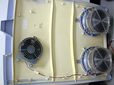
- This section defines the steps necessary for the cover shown
in Figure 1.
Figure 1. Top cover without removable fan section
- Place the top cover on an appropriate flat work surface, and locate the failed fan.
- Disconnect the power cable that connect to the fans on the gantry
top cover.note:
Three cooling fans are mounted on the top covers.
- The two (2) primary fans are attached to the cover in four (4) locations around the fan assembly . You only need to remove the nuts and washers, to remove the fan. Do not remove the fan safety grill which is mounted to the cover assembly.
- Remove the ground wire from the ground stud and disconnect the fan power connection connector.
- Replace the defective fan and reverse the removal process. Connect all removed cables, and securely tighten all removed hardware.
3 Top Cover Fan Replacement (Top covers with removable fan section)
Procedure
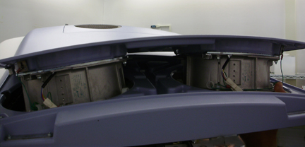
- This section defines the steps necessary for the cover shown
in Figure 2.
Figure 2. Top cover with removable fan section
- Place the top cover on an appropriate flat work surface, and
locate the failed fan.note:
Three cooling fans are mounted on the top covers.
- Disconnect the power cable that connect to the fans on the gantry
top cover.
Figure 3. Top cover with removable section
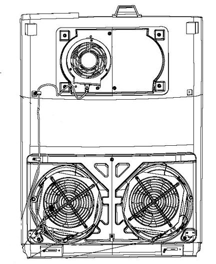
- The two (2) primary fans are attached to the cover in four (4) locations around the fan assembly. You only need to remove the screws at each corner of the fan, to remove the fan. Do not remove the fan safety grill that is mounted to the cover.
- Remove the ground wire from the ground stud.
- Replace the defective fan and reverse the removal process. Connect all removed cables, and securely tighten all removed hardware.
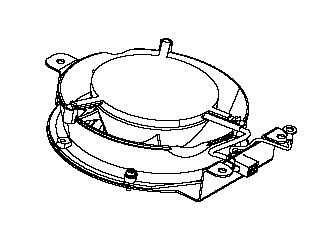
4 Secondary Top Cover Fan Replacement (Both top cover styles)
Procedure
- The fan is attached to the cover in three (3) locations around
the fan assembly with M4 screws. Disconnect the power connector then
remove the hex head screws to remove the fan. Fan may have the power
connector built into frame or loose and may or may not have a ground
connection due to fan style. See Figure 4 or Figure 5 depending on
fan style.
Figure 4. Example Booster fan assembly
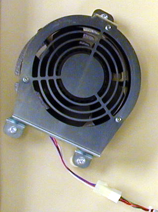
Figure 5. Booster fan assembly
- Replace the defective fan and reverse the removal process. Connect all removed cables, and securely tighten all removed hardware.
5 Finalization
Procedure
- Reinstall top and side covers per cover procedures including
gantry power up steps.
Refer to
- Verify all fans start immediately after a power reset to the gantry. The fans will then either turn off or change to a system defined speed dependent on the current gantry temperature.