- Topic ID: id_15460711
- Version: 2.0
- Date: Nov 8, 2018 1:36:38 AM
GOC6 Series Console - VeRB Upgrade
Prerequisites
Overview
This procedure describes and illustrates the steps necessary to upgrade a GOC6 or GOC6.5 (GOC6 Series) Operator Console with a VeRB Recon Computer using Upgrade Kits 5321434 (for GOC6 Consoles or 5321434-2 (for GOC6.5 Consoles).
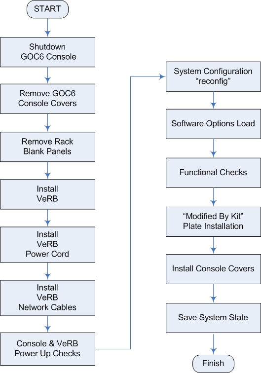
The flowchart in Figure 1 presents the basic upgrade process.
Figure 1. VeRB Upgrade - GOC6 Series Console Flowchart
Please review Section 3.5, Required Conditions, before proceeding with this upgrade procedure.
1 Power Off (Shutdown) Console
Procedure
- Select one of the following methods to power off the Operator
Console:
- If Applications are running, click on the [Shut Down] icon and select [Shutdown].
- If Applications are down, open a Unix Shell using the Toolchest.
Type:
{ctuser@hostname} haltENTER
The Operator Console monitor will display a System Halted message when it is acceptable to power off the Operator Console.
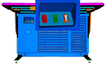
- Power OFF the Operator Console at the front panel switch (Figure 2).
Figure 2. Console Power Switch
- Perform Lockout / Tagout as described in Safety – Equipment Service – Lockout / Tagout / PPE in the LightSpeed VCT Service Manual. For added protection, disconnect the Twist-N-Lock Main Power Cable from rear of console.
2 Remove Console Covers
Procedure
- Move the console away from the wall to allow clear access around the console.
- Remove console’s front and rear covers and set aside.note:
Refer to Replacement > Console GOC6 > Console Cover Removal and Installation in the Lightspeed VCT Service Manual for more details.
- Remove the console’s Keyboard Tabletop and set aside. This will allow better access to the console’s computer rack.
3 Remove Rack Blank Panel
Procedure
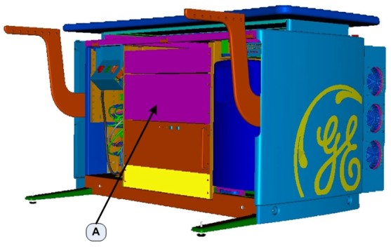
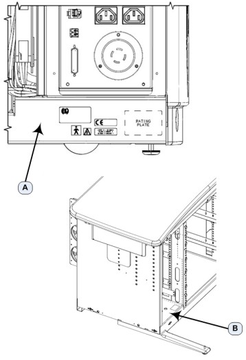
- At the front of the Console, remove the Rack Blank Panel (item A in Figure 3) immediately above the DIG Computer.
Figure 3. Console Rack Blank Panel Location
 note:
note:Save the four (4) 5mm socket cap bolts and washers.
- The Rack Blank Panel is no longer needed. Dispose of it properly.
4 VeRB Computer Installation
Procedure
- Remove the VeRB Computer (5255299-30 FOR GOC6 OR 5255299-31 for GOC6.5) from the shipping container and check that all packaging material has been removed and is not blocking intake fans or ventilation grills on the chassis.
- Lift and slide the VeRB Computer in the front of the console,
sliding the VeRB Computer on the two rack guides already installed
in the console rack. Push the VeRB Computer fully into the console
rack until it is flush with the front of the console rack.note:
If necessary, utilize the recommending lifting tools described in Safety – Equipment Service – Console in the Lightspeed VCT Service Manual.
- Mount the VeRB Computer to the console rack utilizing the four (4) 5mm socket cap bolts and washers removed earlier. Torque to 4.6 N-m.
5 VeRB Power Cable Connections
Procedure
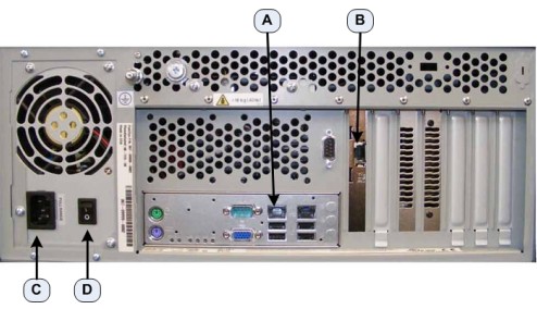
- At the rear of the console, plug the VeRB Computer Power Cable (5314704) into the VeRB Computer (item C in Figure 4).
- Label this end of the power cord “VeRB” using the supplied Cable Labels (5316747-3).
- Check, and if necessary, turn on the VeRB Computer Power Switch
(item D in Figure 4).
Figure 4. VeRB Power and Network Connections
- Run the power cable along the cable tray (item A in Figure 5), directly above the VeRB Computer, to the right side.
Figure 5. VeRB Power and Network Cable Routing
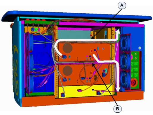
- Label the other end of the VeRB power cord “VeRB J13” using the supplied Cable Labels. Insert this end of the VeRB Computer Power Cable into the console cabinet, along the right side top of the rack, to the Power Distribution Box. (See Figure 5.)
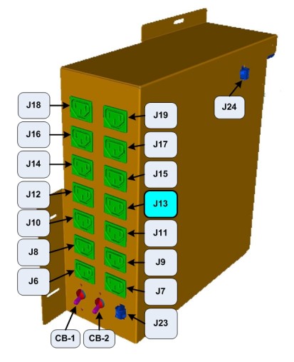
- Plug this end of the VeRB Power Cord into J13 on the Power Distribution
Box (Figure 6).
Figure 6. J13 - VeRB Power Cable Location on Power Distribution Box
6 VeRB Network Cable Connections
Procedure
- At the rear of the console, plug the VeRB Computer Network Cable (5313765) into the VeRB network port (item A in Figure 4). Label this end of the network Cable “VeRB Eth 6” using the supplied Cable Labels (5316747-3).
- At the rear of the console, plug the VeRB Computer RMM Network Cable (5313765) into the VeRB RMM network port (item B in Figure 4). Label this end of the network Cable “VeRB RMM Eth 5” using the supplied Cable Labels.
- Run the Network Cables along the cable tray (item B in Figure 5), directly below the VeRB Computer, to the right side.
- Label the other end of the VeRB Computer Network Cable “Eth 6 VeRB” using the supplied Cable Labels. Insert this end of the VeRB Computer Network Cable into the console cabinet, along right side bottom of the rack, to the Console Network Switch (CNS). (See Figure 5.)
- Label the other end of the VeRB RMM Network Cable “Eth 5 VeRB RMM” using the supplied Cable Labels. Insert this end of the VeRB Computer Network Cable into the console cabinet, along right side bottom of the rack, to the CNS. (See Figure 5.)
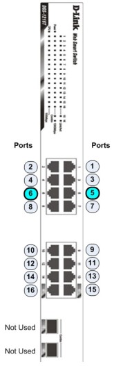
- Connect the VeRB Network Cables into their respective ports
on the CNS. (See Figure 7.)
Figure 7. VeRB Network Cable Connections on Console Network Switch
- Using several tie wraps, secure the VeRB Power and Network Cables to the cable trays along which the cables have been routed. (See Figure 5.)
7 Console and VeRB Power Up Checks
Procedure
- Reconnect the Twist-N-Lock Main Power Cable at rear of console and remove the Lockout / Tagout protection applied earlier.
- Power on the Operator Console at the console’s front panel switch.
- Do not allow Applications to start. During boot-up, cancel Application Startup when the CT Software Auto-start pop-up window appears.
- Verify that the VeRB Computer has powered up and is not displaying
or sounding any POST Errors.note:
See Troubleshooting – Console (GOC6) – VeRB Troubleshooting in the Lightspeed VCT Service Manual for more details.
8 System Configuration (“reconfig”)
In order to ensure proper operation of the VeRB computer, it is necessary to perform the following System Configuration process.
Procedure
- Open a Terminal window and log on as Root.
Type: {ctuser@hostname} su – ENTER
Type the root password and press ENTER
- Launch the Configuration utility:
Type: [root@hostname] reconfigENTER
- The System Configuration Utility launches and the CT Software
Install Utility Window appears.
Figure 8. System Configuration Utility
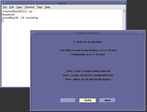
- Click CONFIG in the CT Software Install
Utility Window (Figure 8).
- Click HARDWARE. The Hardware Settings
Screen displays.
Figure 9. Hardware Settings Screen
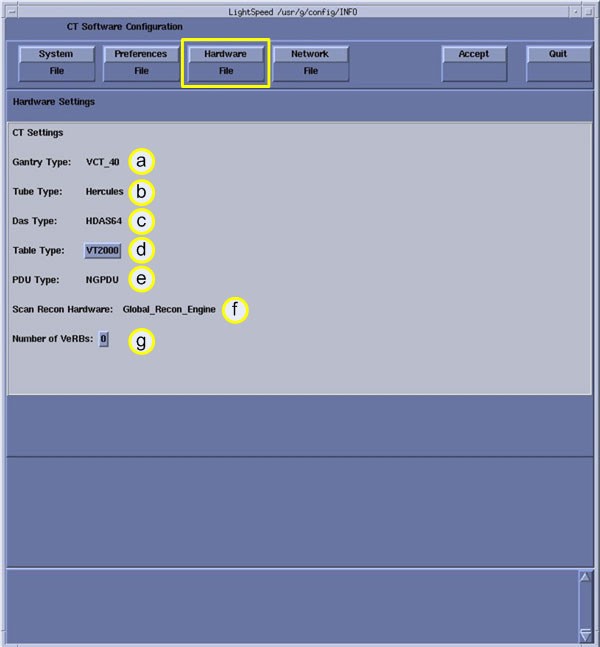
- On the Hardware Settings Screen (Figure 9), change the number of VeRBs (item G) to 1 by clicking on the number.
- Click ACCEPT to accept the changes made.
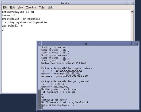
The System Configuration Utility will now reconfigure the system to
include the VeRB Computer. While the configuration is progressing,
the results are displayed in a Shell window (Figure 10) that closes
when the loading process is complete.
Figure 10. Configuration Shell Window
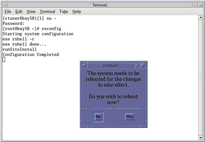
- When the configuration changes are complete, the system displays
a prompt to reboot (Figure 11). Click YES.
Figure 11. Configuration Complete Window
- After Rebooting, the system will automatically log in as ctuser.
- If the Autostart Disabled popup message
appears, select OK and open a Terminal Window.
Type: {ctuser@hostname} stENTER
note:To remove/uninstall a VeRB Computer from the GOC6 Series Console, repeat the process of System Configuration (“reconfig”) and simply change the “Number of VeRB” computers back to “0.” The System Configuration (“reconfig”) script effectively removes the VeRB from the system.
9 Software Options Load
Load new Option Licenses as necessary. Note the following:
-
The procedure for loading option licenses in located in Software GOC6 > Install Software Options in the Lightspeed VCT Service Manual.
-
Though not necessary for performing a VeRB Upgrade, most likely new Option Licenses have been included with the VeRB Upgrade order. Check to make sure all new Option Licenses have been loaded.
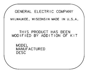
10 Modified By Kit Plate Installation
11 Console Cover Installation
Procedure
- Reinstall Console Front and Rear Covers.note:
Refer to Replacement > Console GOC6 > Console Cover Removal and Installation in the LightSpeed VCT Service Manual for more details.
- Reinstall Console Keyboard Tabletop.
12 Finalization
Procedure
- Save a new System State in accordance with Software GOC6 > Software Installation > System State Save Restore in the LightSpeed VCT Service manual.
- Refer to System Scanning Tests > Functional Checksin the LightSpeed VCT Service Manual to confirm proper operation.