- Topic ID: id_15460094
- Version: 2.0
- Date: Nov 8, 2018 1:35:51 AM
Equipment Service - GOC6 and 6.5 Consoles
Prerequisites
Overview
This guide discusses Console Component Lifting. It describes and illustrates steps to aid in the removal and installation of the computer components in the GOC6 Series Operator Console. By following these guidelines, the risk for injury from lifting heavy computer components will be minimized and allow for a single engineer to safely complete these tasks.
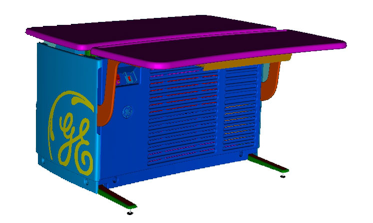
Figure 1. GOC6 & 6.5 Operator Console
1 Console preparation
Procedure
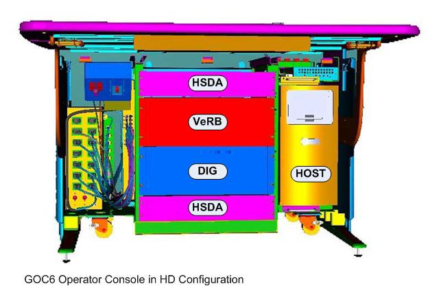
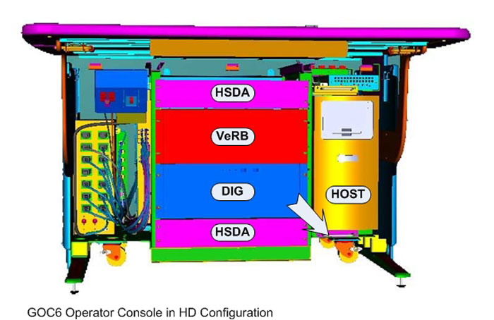
- Only a few of the GOC6 and 6.5 console components that are classified
as Field Replaceable Units (FRUs) need special attention due to their
associated weight. The following illustrations show those components
labeled.
Figure 2. Heavy Console Components
 note:
note:Though this guideline is meant to address safe lifting condition of the aforementioned components, this guideline also illustrates the best method for accessing all the components in the console.
- To allow the best access to the computer components in the console,
the console keyboard table should be removed from the console and
set aside. This allows better access to the front of the console without
interference.note:
Before performing this task, ensure there is a place for the Console Keyboard table to reside without blocking emergency egress path, and there is adequate room to service product(s).
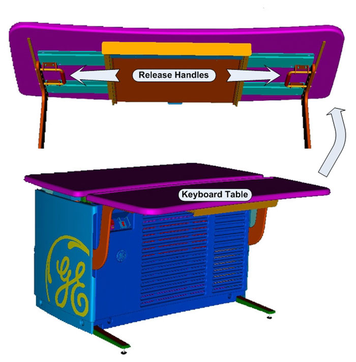
- By pulling on the two (2) release handles under the Console
Keyboard Table, the Keyboard Table can easily be removed from the
support brackets without the use of tools. After releasing the Keyboard
Table, lift the Keyboard Table away from its support brackets and
set it aside being careful not to chip the laminate surface.
Figure 3. Console Keyboard Table Removal
- Remove the operator console front cover as covered in the FRU Replacement Procedures. Unobstructed access should now be available to the components.
2 Lift Assist Recommendations
Procedure
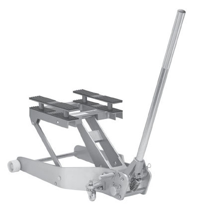
- In the event you believe you are not capable or allowed to lift
any of the identified heavy computer components in Figure 2, then request
that a second person assist in the component removal and installation,
or use a lift assist tool. See examples of two (2) lift assist tools
in the illustration below:
Figure 4. Genie Load Lift
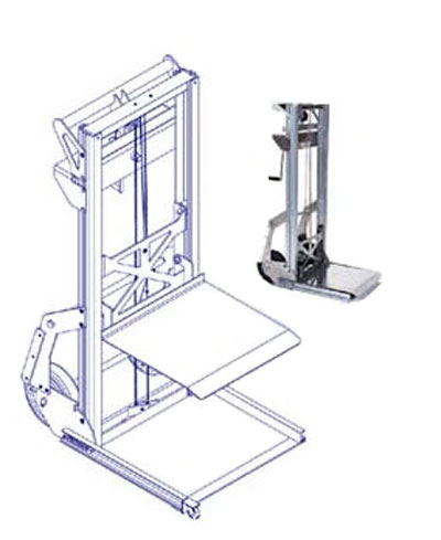
Figure 5. Hydraulic Jack Lift
- Follow prescribed component replacement procedures located in
the Parts Replacement chapter of this manual
for disconnecting mounting hardware and cables attached to the component.note:
All of the above mentioned components are removed from the front of the console. Access to the rear of the console is only necessary to disconnect cabling from these components.
Figure 6. Console Computer Chassis Removal Direction
- Pull the component forward from the console using the handles mounted on each of the component chassis. Do this in a kneeling position to minimize back strain, utilizing any and all personal protection equipment (PPE). Due to ergonomic concerns, it is not advisable to do this in a standing position. Pull the component forward approximately 4-6 inches (15 cm).
- Align the lift assist tool so the tool lifting surface is centered in front and under the component. Adjust the height of the lift assist tool so it just touches the underside of the component.
- Pull the component out away from the console until it sits evenly on the lift assist tool. Move the lift assist away from the console.
- Lower the lift assist tool next to the replacement component and transfer the old component with the replacement.
- Repeat this process in reverse to install the replacement component.
3 Finalization
No finalization steps.