- Topic ID: id_15460410
- Version: 2.0
- Date: Nov 8, 2018 1:38:20 AM
Display Assembly Replacement
Prerequisites
Overview
This procedure defines the steps necessary to replace the gantry display panel.
Procedure
- Move table to its home position.
- Remove gantry right side cover.
Refer to
- Turn OFF the Axial Drive, HVDC and 120 VAC switches on the gantry’s Service Switch Panel.
- Remove the gantry left side cover, top covers and front cover.
- Remove the cables connected to the display assembly.
Figure 1. Display Mount to Front Cover
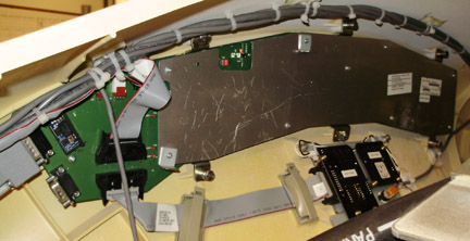
- Loosen the six (6) screws that fasten the display assembly to the cover. Care should be taken to loosen all screws.
- Position the new display panel and secure with the six (6) captive screws. Take care not to overtighten as the screws can break.
- Reconnect the cables to the display panel.
- Install the gantry front cover, top covers, and left side cover.
Refer to
- Enable 120 VAC HVDC and Axial Drive service switches from the
service switch panel. Press the table drives enable button on the
lower right corner of the service switch panel.
Watch the front cover displays during gantry power up. Make sure all the displays are activated during the power up sequence.
- Install the gantry right side cover.
Finalization
- Perform a System Scanning Test from the Functional Checks menu of the service manual to ensure system operation.