- Topic ID: id_15460904
- Version: 2.0
- Date: Nov 8, 2018 1:38:00 AM
Disk Array (JBOD) FRU Replacements
Prerequisites
Overview
This module contains the following replacement procedures for the GOC5 VCT Operator Console Scan Data Disk Array:
-
Replacement of Scan Data Disk Array (JBOD) Chassis (without Hard Disk Drives)
Replacement of Scan Data Disk Array (JBOD) Chassis (without Hard Disk Drives).
note:Power Supplies, Cooling Modules and Controller are not long supplied as replaceable parts.
-
Replacement of an individual Scan Data Hard Disk Drives
Replacement of an individual Scan Data Hard Disk Drives.
-
Upgrade of JBOD Assembly (5114536 to 5114536-40, Entire JBOD Assembly with Hard Disk Drive Swap)
Upgrade of JBOD Assembly (5114536 to 5114536-40, Entire JBOD Assembly with Hard Disk Drive Swap)
1 Replacement of Scan Data Disk Array (JBOD) Chassis (without Hard Disk Drives)
The following procedures are specifically created for the original JBOD Chassis (5114536–20), the procedural step for replacing the JBOD Chassis using the alternative (5114536–30) is the same except for small changes noted in the procedures below. Note: if upgrading from a 5114536–20 to a 5114536–30 JBOD chassis, disk drive locations will be different. See Section 4.6 for details.
1.1 Power-Off (Shut Down) the Console
Procedure
- Select one of the following methods to Power OFF the Operator
Console:
- If Applications are up, select the Shut Down icon and then select Shutdown.
- notice
- If Applications are down, open a Unix Shell at the Toolchest.
Type:
{ctuser@ hostname } halt

- The Operator Console monitor will display a System halted message when it is acceptable to power OFF the Operator Console.
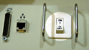
- Power OFF the Operator Console at the
front panel switch. (Refer to Figure 1.)
Figure 1. Power Switch
1.2 Remove the Old Scan Data Disk Array (JBOD) Chassis
Procedure
- Remove the front and rear Operator Console cover.
- Remove all rear cable connection to the Disk Array (JBOD) Chassis. Verify each cable is present and clearly marked, if necessary add a label for clarity.
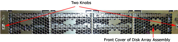
- Remove the front cover of the Disk Array (JBOD) Chassis.note:
Alternative JBOD Chassis (5114536–30) does not have a front cover. Skip step.
Turn the two (2) knobs on the front cover to the horizontal position, then remove the Disk Array front cover.
Figure 2. Disk Array Front Cover
- Remove and retain the four (4) front mounting screws.
- notice
- Remove each disk from the JBOD Chassis individually, and clearly mark them so that they can be returned to the same slot location in the new replacement JBOD.
- Slide out the Disk Array (JBOD) Chassis.
|
1.3 Install the New Disk Array (JBOD) Chassis
Install the replacement Disk Array (JBOD) Chassis in the Operator Console.
Procedure
- Slide the Disk Array (JBOD) Chassis into the Operator Console.
- notice
- Return each Disk or empty sled to its proper position inside the Disk Array (JBOD) chassis.
- Replace the four (4) front mounting screws on the front of the Disk Array (JBOD) Chassis.
- Replace the front cover screen to the Disk Array (JBOD) Chassis.note:
Alternative JBOD Chassis (5114536–30) does not have a front cover. Skip step.
- Replace all rear cable connections to the Disk Array (JBOD)
Chassis.
See Figure 2.
note:All cable connector screw-locks must be finger-tightened, only. Do NOT use any tool to tighten cable screw-locks. Verify that the SCSI Cable is on straight.
|
1.4 Test the Disk Array
Procedure
- Perform all Disk Array RAID Tests per Disk Array RAID Testing
- Continue with Sections 4.4, 4.5 and Finalization.
2 Replacement of an individual Scan Data Hard Disk Drives
The following procedures are specifically created for the original JBOD Assembly (5114536), the procedural step for replacing the Scan Data Hard Disk Drive in the alternative JBOD Assembly (5114536–40) is the same except for small changes noted in the procedures below.
2.1 Power-Off (Shut Down) the Console
Procedure
- Select one of the following methods to Power OFF the Operator
Console:
- If Applications are up, select the Shut Down icon and then select Shutdown.
- notice
- If Applications are down, open a Unix Shell at the Toolchest.
Type:
{ctuser@ hostname } halt
- The Operator Console monitor will display a System halted message when it is acceptable to power OFF the Operator Console.
- Power OFF the Operator Console at the front panel switch. (Refer to Figure 1.)
2.2 Remove the Old Scan Data Disk Drive which will be replaced
Procedure
- Remove the front Operator Console cover.
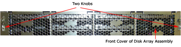
- Remove the front cover of the Disk Array (JBOD) Chassis: note:
Alternative JBOD Chassis (5114536–30) does not have a front cover. Skip Step.
Turn two knobs on the front cover to horizontal position, then take off the front cover from the Disk Array.
Figure 5. Front Cover of Disk Array Assembly
- Pull the Scan Disk Drive (with sled) out the Disk Array (JBOD).
Figure 6. Remove Disk Drive (with Sled)
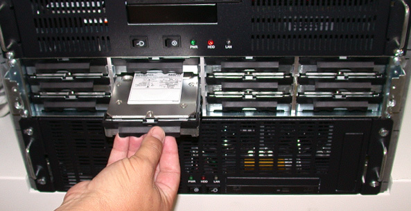
2.3 Install the New Scan Data Disk Drive (with sled)
Procedure
- Insert new Scan Disk Driver (with sled) in the Disk Array (JBOD) at the original position of the old disk drive.
- Replace the four (4) front mounting screws on the front of the Disk Array (JBOD).
- Replace the front cover screen to the Disk Array (JBOD) Chassis.note:
Alternative JBOD Chassis (5114536–30) does not have a front cover. Skip Step.
2.4 Power ON the Console
Procedure
- Power ON the Operator Console at the front switch.
- At the VDARC Node verify the front panel Power LED is ON. If not, press the front panel power switch (hold 3-10 seconds) to apply power to the VDARC Node.
- At the VIG Node verify the front panel Power LED is ON. If not, press the front panel power switch (hold 3-10 seconds) to apply power to the VIG Node.
- At the Disk Array (JBOD) verify two green LEDs at rear panel is on. If not, press the two power switches at rear panel to apply power to the Disk Array (JBOD).
- Stop Applications from auto-starting at the 5 second Warning Message.
2.5 Test the Disk Array RAID
Procedure
- Perform the Create, Assemble and Query Disk Array RAID Tests per Disk Array RAID Testing
- Continue with Sections 4.4, 4.5 and Finalization.
3 Disk Array RAID Testing
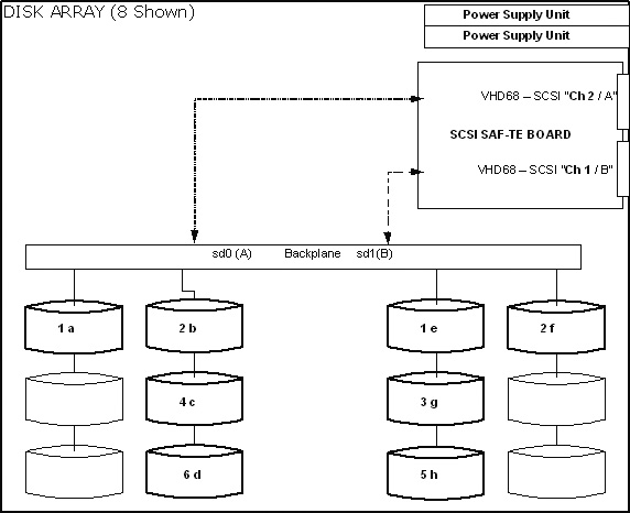
3.1 Verify Disk Present and Mounted
The following procedure was specifically created for the original JBOD Assembly (5114536). The procedure below are still the same for the alternative JBOD Assembly (5114536–40), but command outputs in table will vary from shown.
Procedure
- Open a Unix Shell as root and type the following commands to
verify 8 disks are present. Additionally, /dev/md0 can be checked to see if /raw_data is mounted
using the df or df /raw_data command.
- {ctuser@ hostname } rsh darc
- {ctuser@darc} df
- [root@darc] sg_map –i -x
- Verify Disks and Mount State Command Output:
3.2 Create/Repartition the Scan Data Disk Array
The following procedure was specifically created for the original JBOD Assembly (5114536). The procedure below are still the same for the alternative JBOD Assembly (5114536–40), but command outputs in table will vary from shown.
A special create command (sudo gre-raid -c –z) is available for sites that experience issues with the individual disk drive (a good drive the system has tagged as bad). This command still destroys all data by repartitioning or creating the Disk Array. Additionally, it erases the Disk drive serial numbers for the Disk Array (JBOD) allowing reuse of a Disk Drive. Do not use this command on intermittent or faulty Disk Drives. Replace bad Disk Drives. Do Not perform this command if Patient data is not fully backed up. Application Software must be down to perform the create command for the Disk Array.
Procedure
- Open a Unix Shell and type the following:note:
The create command (sudo gre-raid -c) destroys all data by repartitioning or creating the Disk Array. Do Not perform this command if Patient data is not fully backed up. Application Software must be down to perform the create command for the Disk Array.
{ctuser@ hostname } rsh darc
{ctuser@darc} sudo gre-raid -c
************************** Warning ******************************
* If a new disk array is created, all scan data on the current *
* disk array will be lost. *
*****************************************************************
Are you sure you want to create a new disk array (yes/no)? yes
- Verify the create partitions diagnostic passes and all output looks good.
- Perform the assemble and query commands if the create has been
successful.
3.3 Assemble the Scan Data Disk Array
The following procedure was specifically created for the original JBOD Assembly (5114536). The procedure below are still the same for the alternative JBOD Assembly (5114536–40), but command outputs in table will vary from shown.
Procedure
- Open a Unix Shell and type the following:note:
Application Software must be down to perform the assemble commands for the Disk Array. The Operator Console can not be scanning or manipulating Scan Data during the testing.
{ctuser@ hostname } rsh darc
{ctuser@darc} sudo gre-raid -a
- Verify assemble diagnostic passes and all output looks good.
- Perform the query command if the assemble has been successful.
3.4 Query the Scan Data Disk Array
The following procedure was specifically created for the original JBOD Assembly (5114536). The procedure below are still the same for the alternative JBOD Assembly (5114536–40), but command outputs in table will vary from shown. Click on this media file 4930332.pdf to see differences between the between the original and alternative JBODs when executing the gre-raid –q command. Note: The command output for the alternative JBOD will not correctly represent the physical hard drive locations.
Procedure
- Open a Unix Shell and type the following:note:
A query can be performed at any time with Application software up or down. The preferred method is to test with Application software down. The Operator Console can not be scanning or manipulating Scan Data during the testing.
{ctuser@ hostname } rsh darc
{ctuser@darc} sudo gre-raid -q
- Verify query diagnostic passes and all output looks good.
- Type: {ctuser@darc} exit
- Close the Unix Shell: {ctuser@hostname} exit
4 Start Applications
Procedure
- {ctuser@ hostname } st
- If Application software fails with a halt due tot the Disk Array:
- Turn Off power at the front switch on the Operator Console.
- Wait one minute for the Disk Array to settle.
- Turn On power at the front switch on the Operator Console.
- Do Not allow CT Application Software to start-up.
- View the gesyslog. Locate the startup time of Application software that just halted. Look for a message related to gre-raid. If the Disk Array is the problem, a message will be present identifying a failure with the gre-raid (Disk Array).
5 Retro Recon Test
The Reconstruction (not Scan) portion of the system can be tested at this point.
Procedure
- Click on the RETRO RECON selection on the left monitor.
- Click on RAT GOLD series.
- Click on SELECT SERIES.
- Click on CONFIRM.
Verify the image(s) reconstruct and are displayed.
- Click on QUIT.
6 Upgrade of JBOD Assembly (5114536 to 5114536-40, Entire JBOD Assembly with Hard Disk Drive Swap)
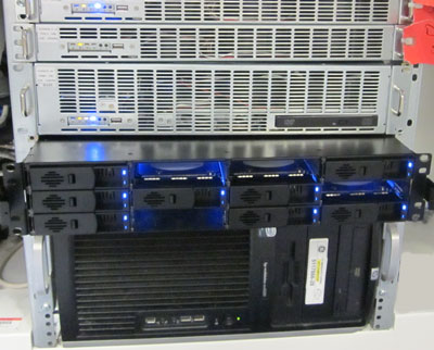
Due to part obsolescence, the JBOD Assembly (5114536 – Scan Data Disk Array) is no longer manufactured. A new supplier has been identified and a new JBOD Assembly has been cut into forward production for the GOC5 Operator Consoles. The new JBOD Assembly (5114536-40) functions the same as the original JBOD, using the same Hard Disk Drives, but has significant hardware changes. In the event the original JBOD Chassis FRU (5114536–20) is not longer available, the JBOD Assembly will need to be upgraded to the alternative version.
Figure 7. Alternative JBOD Assembly (5114536-40)
Procedure
- Remove old JBOD Assembly.
- Disconnect original SCSI Cables from DARC Computer and original JBOD (Discard).
- Disconnect the two (2) AC Power Cables from original JBOD Chassis.
- Remove original JBOD Assembly (with Hard Drives) from operator console.
- Install new JBOD Assembly
- Install new JBOD Chassis (Note: will not contain Hard Drives).
- Install new SCSI Cables between new JBOD Chassis and DARC Computer.
-
DARC CH 1B > JBOD Host 1
-
DARC CH 2A > JBOD Host 2
-
- Plug in two (2) AC Power Cables to new JBOD Assembly.
-
Power cable labeled “J4 Disk Array Left” > New JBOD Upper Power Interface
-
Power cable labeled “J11 Disk Array Right” > New JBOD Lower Power Interface
-
- Swap Hard Drives between original and new JBOD Assembliesnote:
To avoid recreating array and scan database, hard drive transfer between original and new JBOD chassis must follow the following pattern. The illustrations below are representative of bay locations of the two units. The hard drives shall be installed in the bays identified. If the transfer is not performed correctly or hard drives are replaced in the process, a new scan data array and database must be created.
-
Remove Hard Drive in Sled for original JBOD Chassis
-
Remove Hard Drive from Sled
-
Remove empty new Sled from new JBOD Chassis
-
Install Hard Drive into new Sled
-
Install new Sled with Hard Drive into new JBOD Chassis in appropriate bay location
note:Perform the process on one hard drive, and then repeat for the remaining drives. Do one drive at a time; as to not loose track of hard drive bay location.
-
7 Finalization
Procedure
- Take some scans (e.g., scout, axial and helical).
Verify the image(s) reconstruct and are displayed.
- Install the cover of Disk Array (JBOD), if removed.
- Install the front and rear Operator Console covers.