- Topic ID: id_15460801
- Version: 2.0
- Date: Nov 8, 2018 1:37:53 AM
Console Network Switch Replacement
Prerequisites
Overview
This procedure describes and illustrates the steps necessary to replace the Console Network Switch (Illustrations 1 & 2).
Figure 1. Console Network Switch (5263798)
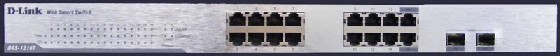
Figure 2. Console Network Switch (5263798-2)

1 Power-Off (Shut Down) the Console
Procedure
- Select one of the following methods to power off the Operator
Console:
-
If applications are running, click the Shut Down icon and select Shut Down.
-
If applications are down, open a Unix shell using the Toolchest. Type: {ctuser@hostname} halt and press Enter.
The Operator Console monitor will display a System Halted message when it is acceptable to power off the Operator Console.
-
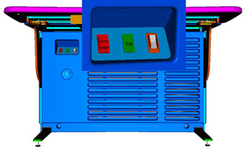
- Power OFF the Operator Console at the front panel switch. (See Figure 3.)
Figure 3. Console Power Switch
- Perform prescribed Lockout/Tagout procedure. For added protection,
disconnect the Twist-N-Lock Main Power Cable from the rear of the
console.
2 Remove Console Network Switch (CNS)
Procedure
- Remove the front and rear Operator Console Covers per prescribed cover removal procedure.
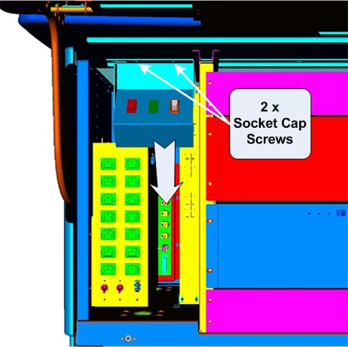
- To allow the removal of the CNS from the console, loosen and
remove the two (2) 4mm socket cap mounting screws holding the console
Power Switch Assembly to the console chassis and set the Power Switch
Assembly aside.
Figure 4. Power Switch Assembly Mounting and Removal
- Remove the Ethernet network cable connections to the CNS being
replaced.note:
Verify that all cables are labeled and clearly marked; if necessary, add a label for clarity.
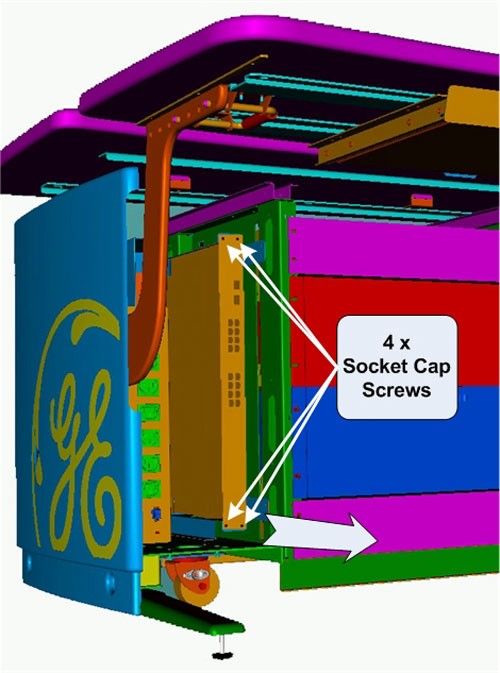
- Remove the four (4) 5mm socket cap mounting screws from the
front of the CNS, which hold the CNS in its mounting bracket. Remove
the power cord at the rear of the CNS.
Figure 5. CNS Mounting and Removal
- Slide the CNS forward (out the front of console) and set aside.
3 Install the Replacement CNS
Procedure
- Slide the replacement CNS into the Operator Console from the front.
- Reinstall the four (4) 5mm socket cap mounting screws to secure the CNS. Torque to 4.6 N-m.
- Mount the power cord to the rear of the console.
- Reinstall the Ethernet cable connection(s) to their original
locations.note:
FOR PROPER OPERATION, IT IS CRITICAL THAT ALL ETHERNET CABLES BE PLUGGED INTO SPECIFIC LOCATIONS ON THE CNS.
Figure 6. CNS (5263798) Cable Connections and Destination
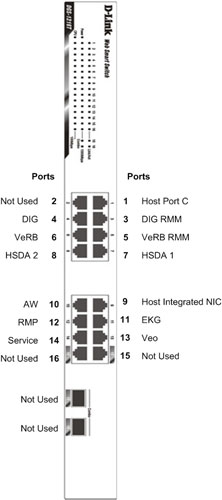
Figure 7. CNS (5263798-2) Cable Connections and Destination
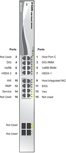
For cabling details, refer to the appropriate interconnect drawing located in the System Diagrams folder of this service methods publication.
- Replace the Power Switch Assembly removed earlier using the
two (2) 4mm socket cap mounting screws to hold the Power Switch Assembly
to the console chassis. Torque to 2.9 N-m.
4 Power-On the Operator Console
Procedure
- Reconnect the Twist-N-Lock Main Power Cable from rear of console and remove Lockout Tagout protection applied earlier.
- Power ON the Operator Console at the console front panel switch.
5 Verify Replacement CNS Operation
Procedure
- Visually verify the CNS front panel Power LED is illuminated.
Figure 8. CNS (5263798) Front Panel Indicators
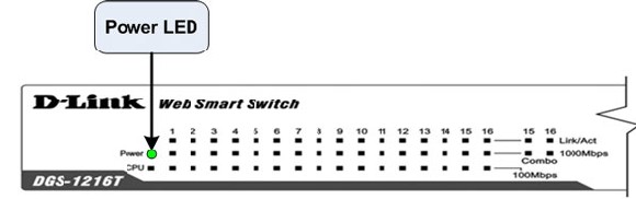
Figure 9. CNS (5263798-2) Front Panel Indicators
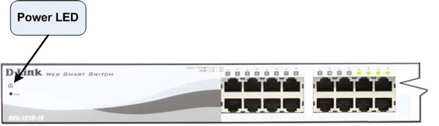
- Visually verify that all appropriate Port LEDs show active links.
The CPU LED should be blinking during normal operation.note:
Refer to Console Network Switch Troubleshooting if any problems are suspected.
6 Finalization
Procedure
- Refer to System Scanning Test to confirm proper operation.
- Reinstall Console Front and Rear Covers.