- Topic ID: id_15460924
- Version: 2.0
- Date: Nov 8, 2018 1:37:49 AM
Console Cover Removal and Installation
Prerequisites
Overview
This procedure shall be followed when removing or installing covers on the Console – GOC6.6 Chassis.
1 Console Preparation
Each section below will give instructions to remove and install each console covers and tabletop assemblies. These covers and tabletop assemblies can be removed independently.
Procedure
- From the Application Desktop, shut down the system.
- Turn off Console power using the front panel switch.note:
It is recommended that LOTO procedures be followed at this point if cover removal of Console is being performed for the purpose of replacing components.
For procedures, see Equipment Service - Lockout-Tagout-PPE.
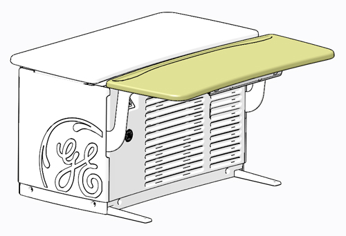
2 Keyboard Table Top
Figure 1. Console Keyboard Table Top
2.1 Keyboard Table Top Removal
Procedure
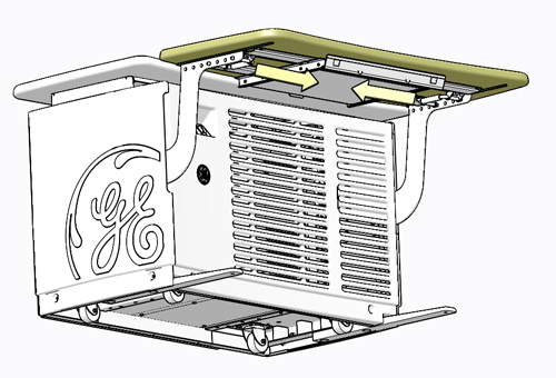
- Locate the spring-loaded latches at either end of the underside
of the keyboard table top. Pull the latches inward (toward center
of table top).
Figure 2. Keyboard Table Top Release Latch Locations
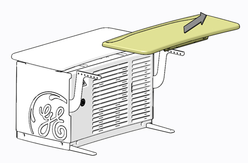
- Lift Keyboard Table Top up and away from console.
Figure 3. Console Keyboard Table Top Removal
2.2 Keyboard Table Top Installation
Procedure
- Position Keyboard Table Top on the brackets so the latches align with the holes.
- Pull and release the latches, so the pins fully engage into
the bracket holes (pins should protrude beyond outside edge of bracket).
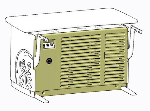
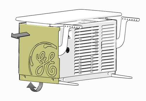
3 Front Cover
Figure 4. Console Front Cover
3.1 Removal Procedure
Procedure
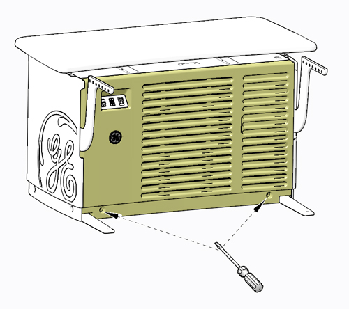
- Loosen two (2) slot head captive screws at bottom of GOC6.6
chassis.
Figure 5. Console Front Cover Capture Screw Location
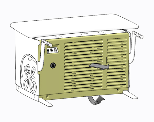
- Rotate bottom of cover outward and lift upward until it the
cover is free of the GOC6.6 chassis cover hangers and set aside.
Figure 6. Console Front Cover Removal
3.2 Installation Procedure
Procedure
- Engage front cover on cover hangers on top front of GOC6.6 chassis.
- Swing cover down into place, position left or right as required to align mounting points.
- Tighten two (2) slot head captive screws at bottom of GOC6.6
chassis.
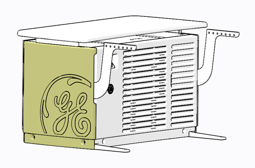
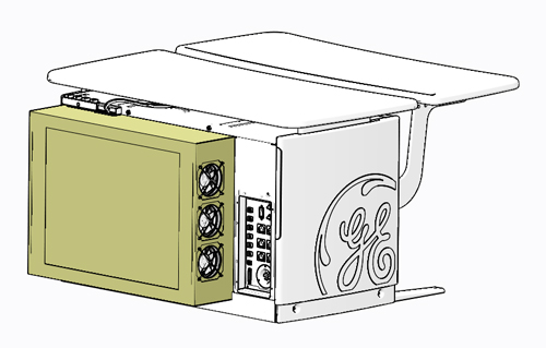
4 Side Covers
Figure 7. Console Side Cover
4.1 Removal Procedure
Procedure
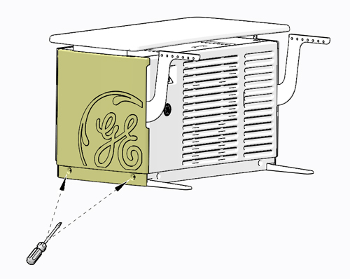
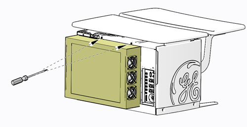
- Loosen the two (2) slot head captive screws at the bottom of
the side cover.
Figure 8. Console Side Cover Capture Screw Location
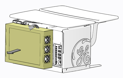
- Rotate bottom of cover outward and lift upward until it the
cover is free of the GOC6.6 chassis cover hangers and set aside.
Figure 9. Console Side Cover Removal
4.2 Installation Procedure
Procedure
- Engage side cover on cover hangers on top side of GOC6.6 chassis.
- Swing cover down into position, position left or right as required to align mounting points.
- Tighten the two (2) slot head captive screws at the bottom,
to hold the side cover to the GOC6.6 chassis.
5 Rear Cover
Figure 10. Console Rear Cover
5.1 Removal Procedure
Procedure
- Loosen two (2) Phillips head captive screws at top of rear cover.
Figure 11. Console Rear Cover Capture Screw Location
- Tilt cover backward, so top moves away from GOC6.6 chassis.
Lift cover away, so that tabs disengage from bottom lip of opening.
Figure 12. Console Rear Cover Removal
5.2 Installation Procedure
Procedure
- Engage rear cover so that cover tabs engage the bottom lip of GOC6.6 chassis.
- Swing cover up into position.
- Tighten two (2) Phillips head captive screws at the top, to
hold the rear cover to the GOC6.6 chassis.
6 Finalization
Remove LOTO on Console, if applied. For procedures, see Equipment Service - Lockout-Tagout-PPE. Return power to the console by turning on the front panel power switch.