- Topic ID: id_15460881
- Version: 2.0
- Date: Nov 8, 2018 1:38:19 AM
Breathing Light Assembly Replacement
Prerequisites
Overview
This procedure defines the process to replace the breathing light assembly on the front cover.
Procedure
- Remove gantry right side cover.
Refer to
- Turn OFF the Axial Drive, HVDC and 120 VAC switches on the gantry’s Service Switch Panel.
- Remove the gantry left side cover, top covers, scan window and front cover.
- If the breathing light assembly has a microphone cover installed
as shown below, move the microphone cover to the new breathing light
assembly. Refer to the Microphone Cover Installation/Replacement Procedure for full installation details. If the system does not
have a microphone cover, proceed to Step 5.
Figure 1. Installed Microphone Cover
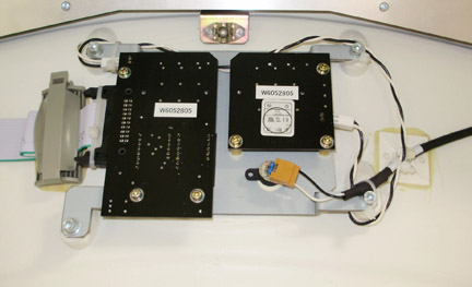
- On the back side of the front cover, remove the cables on the
breathing light assembly.
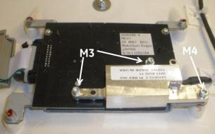
Figure 2. Gantry Breathing Light Assembly

Figure 3. Breathing Light Assembly mounts
- With a 3 mm Hex wrench, remove four (4) screws that fasten the breathing light assembly to the cover.
- Replace the breathing light assembly panel with the 4 screws and reconnect the 2 cables.
- Install the gantry front cover, scan window, top covers and
left side cover.
Refer to
- Enable 120 VAC HVDC and Axial Drive service switches from the service switch panel. Press the table drives enable button on the lower right corner of the service switch panel.
Finalization
- Check the gantry displays during gantry power up to make sure the breathing lights turn on/off during the reset.
- Install the gantry right side cover.