- Topic ID: id_15460662
- Version: 2.0
- Date: Nov 8, 2018 1:38:03 AM
Axial Drive Conversion
Prerequisites
Overview
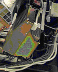
This procedure describes the steps necessary to install a new axial drive assembly (PN: 5344400) as an upgrade into the gantry from axial drive (PN: 2217930).
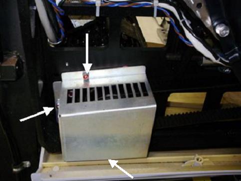
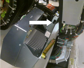
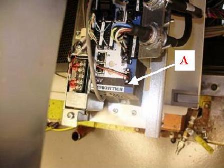
Figure 1. Drive Assembly to be Installed Per This Procedure
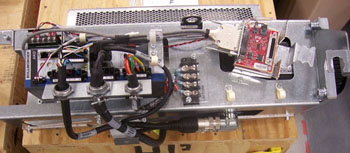
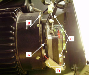
Figure 2. Drive Assembly to be Removed Per This Procedure
1 Preparation for Conversion
Procedure
- notice
- Remove gantry right side cover and disable Axial drive, HVDC
and 120VAC service switches from the service switch panel.
Refer to Replacement > Gantry > Enclosure > Cover Removal Procedures.
- Perform all required LOTO activities to remove all power from the gantry.
- Remove the gantry left side, top, front and rear covers. Connect the cover E-stop circuit to the terminators on the gantry.
- Remove right and rear base covers.
Refer to Replacement > Gantry > Enclosure > Cover Removal Procedures.
- notice
- Remove the lower slip ring cover by loosening the captive screws.
- Remove the front right screw and two rear middle screws of the gantry tilting bottom cover to allow removal of the drive pulley cover.
- Remove the right side tilting safety cover panel with a 5mm hex wrench for easier access to the drive module.
- Position gantry such that the tube is at the 6-7 o'clock position (tube at bottom of gantry) so that there are minimal obstructions from the hoist setup to the drive/motor assembly position. The chain of the hoist will then rest against the balance weight stack and not hit other components during use.
- Engage the rotating assembly indexer lock to prevent gantry rotation during this procedure.
 |
|
2 Removal of existing drive assembly
Procedure
- Disconnect the control cable from the backside of the Axial
Drive Module (ADM) assembly. Refer to Figure 3.
Figure 3. Axial Drive Module Rear View
- Remove the ADM front cover by loosening the two (2) thumb screws and sliding the cover up and off the drive module.
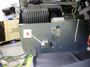
- Disconnect the 3-phase VAC power connections at TB1 R, S, T,
Grnd. See Figure 4 for this and subsequent steps for terminal block locations.
Figure 4. Cable Connections
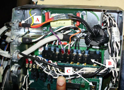
- Disconnect the axial dynamic brake cable connections at TB1 DC+, DC- and TB3 24, 25.
- Using a flat head screwdriver, carefully loosen and fully remove the lock nuts from the dynamic brake line and power line cable bulkhead clamps (first and third from the top), 2 total. Reference Figure 4.
- With lock nuts removed from the bulkhead clamp, reach out of the sheet metal side and pull the cable up through the slots such that the cables are now free from the drive module housing. Carefully cut and remove cable ties as needed.
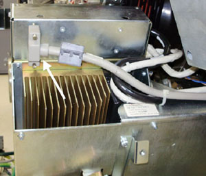
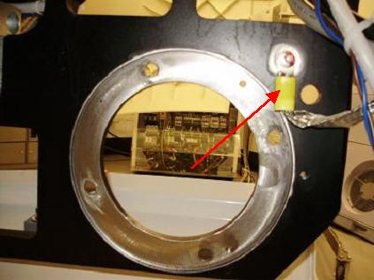
- Disconnect the transformer 120V 2 PIN molex and DC molex connections
on the dynamic brake. These will no longer be used with the installation
of the new axial drive. Refer to Figure 5.
Figure 5. Axial Holding Brake Assembly
- Disconnect the molex connection at the holding brake relay (blue and brown) between the drive module and the axial motor.
- Remove the drive gear cover by removing the two or three M6
hex screws, flat washers and lock washers with a 5mm hex wrench. Refer
to Figure 6.
Figure 6. Gear Cover
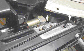
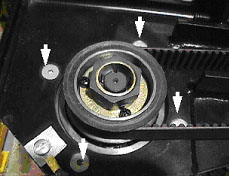
- Loosen the axial drive belt using the two steps below. Refer
to Figure 7.
- Using a 10 mm hex key, or hex bit socket, loosen the two (2) mounting screws on the belt tension plate.
- Using a 6 mm hex key, or hex bit socket with a 12 inch extension,
fully loosen the elongated hex screw to loosen the drive belt.
Figure 7. Threaded Rod and Two Mounting Screws
- Remove the drive belt from the drive gear. Take care to not disturb the teeth engagement along the rotating assembly.
- Remove ground braid from frame with a 5mm hex wrench and discard
. Refer to Figure 8.
Figure 8. Ground Braid to be Removed and Discarded
- Assemble the gantry tube hoist frame and install hoist. Use
a strap on the hoist wrapped around the drive assembly to support
the motor. note:
If the frame of the old axial drive unit has a slot as shown in Figure 9 then the hook can be attached to the slot and the strap is not necessary. Not all older motor drive assemblies have this slot available.
Figure 9. Potential Hoist Hook Slot
 warning
- Using a 7/32 inch hex bit socket, remove the four (4) hex screws
mounting the motor to the gantry frame. Refer to Figure 10.note:
Screws may be very tight. Be careful when initially loosening motor mount screws.
Figure 10. Removing the Four (4) Hex Screws Will Release Motor
- caution
- Guide the motor assembly out of the gantry and set aside. Leave the hoist assembly set up as it will be required for the installation of the new drive.
- Remove lower Cantrell (latch) bracket from the assembly. You
will need to reuse this bracket on the new assembly on installation.
Refer to Figure 11.
Figure 11. Safety Cover Bracket and Lower Cantrell to be Reused
- Pull all remaining cables through the back of the gantry frame for installation.
3 Installing Axial Drive Assembly
For installation procedure, refer to 2010 Axial Drive Assembly Replacement, Section 4.3 and 4.4.
Procedure
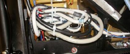
- For additional routing, bundle excess cabling in the back of the frame and connect to frame with cable ties.
- Do the same with entire brake cable that was removed from the
dynamic brake. Refer to Figure 12.
Figure 12. Bundling Excess Cabling
4 Reassembly of Gantry
Procedure
- Replace tilting bottom cover and tilting gantry safety cover.
- Remove LOTO to restore system power.
- Turn on the 120VAC service switch from the service switch panel.
- When power is turned to ON, a code “o2” should display
on the axial drive window. Refer to Figure 13.
Figure 13. “o2” Code on Axial Drive display
- Turn off the 120VAC service switch from the service switch panel.
- Install the right side tilting gantry cover.
- Disengage the rotating assembly lock and replace the bottom cover and lower slipring cover.
- Install the gantry front and rear covers, scan window, top and left side covers.
- Turn on the 120VAC, axial drive and HVDC service switches from the service switch panel.
- Install the gantry right side cover.
5 Finalization
Procedure
- Perform a Fastcal from the Daily Prep button of the scan display.
- Run the System Scanning Test from the Functional Checks procedure list.
- Plug in any options the customer has to the interface panels as applicable for your site. Perform any defined functional checks for the options plugged into the interface panels.