- Topic ID: id_15460642
- Version: 2.0
- Date: Nov 8, 2018 1:36:21 AM
Align the Table to the Gantry
Prerequisites
Overview
1 Leveling the Table
 |
|
If the floor covering was not properly removed with the glue cleaned off, or the levelers were not centered over the floor cutouts, the leveler may become trapped against the edge of the floor covering, causing the table to become unlevel. If this happens, move the table and enlarge the 102 mm (4 in.) floor cutout for the table. Glue removal is important and aids in moving the table to its final location in accordance with the floor levelness specification.
Procedure
- Have the table side panels removed and a ratchet, 1-1/8 in. socket, and a 2 ft. level ready to use.
- Turn on the laser’s “I” beam (vertical beams) by pressing the ON button 2 times.
- The table on the dollies should be resting on the floor, and the laser beam visible on the cradle. The laser light should now shine down the cradle onto the rear vertical target. Moving the table on the dollies by raising and lowering makes it easier to center the table right-to-left.note:
When using the table dolly to move the table, be sure that the shipping bolts are still attached to the adjuster leveler feet. This prevents the adjuster levelers from gripping on the floor adhesive, making it difficult to move.
- Move the table so that the base is roughly centered over the scan center line, the front edge of the table base is on the 26.5 in. (± 0.25 in.) line, and the table is resting on the floor. Check that the leveling feet are centered in the cutout circles.
- Carefully move the table so that the cradle front center line and the back target are aligned. You may need to raise the table to move it. When aligned, lower the table to the floor.
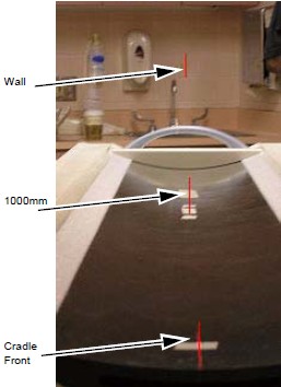
- If not already done, measure 1000 mm from the front of the cradle, and place a piece of tape under the laser center line. Carefully mark a line along the laser line when the table is centered.
- The laser beam should now connect the cradle front centerlines, the 1000 mm cradle center line, onto the rear alignment tool vertical center, and finally onto the alignment centering mark placed on the wall, when properly centered along the center line. Use the centering alignment line on the wall to be sure the laser is still centered. If the alignment line on the wall is NOT on the original mark, readjust the laser and repeat the above steps (see Figure 1).
 caution
- The table should be completely on the floor and resting on all 4 levelers.
Figure 2. Table with Bubble Level
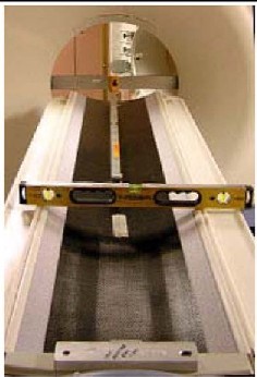
- Raise or lower the table as needed using the front and rear levelers and level the cradle horizontally in the front and back locations (refer to Figure 2):
- First, horizontally across the cradle at the front of the cradle.
- Second, horizontally across the cradle at the 1000 mm mark on the cradle.
- When the cradle is roughly level in both locations, leave the level on the cradle horizontally.
- Level the cradle front to back using a 4 ft.level placed in the center of the cradle. These two leveling actions often conflict and a few iterations may be required.
This process is complete when:
-
The cradle is still centered on the front, mid, and rear marks.
-
The cradle is leveled horizontally (across table) front and back (with the bubble centered between the lines.)
-
The bubble is centered between the lines in the Y direction along the length of the cradle.
-
The laser is still centered on the wall center line.
-
The table is still on the 26.5 in. line and the levelers are not resting on the flooring.
-
The laser is the same as in Step 7.
note:The leveling process may take several iterations of #id_SL2955302-1096870/SL2955303-1096870 through Step 10. Patience and accuracy is required to properly complete this process.
-
- When completed, turn off the laser tool.note:
Do not remove the table dollies.
2 Cradle/Table Parallel Check
Procedure
- caution
- Confirm that there is a centerline on the table at 1000 mm measured from the black dot on the front of the table.
- If the line is not present, turn on the laser and using masking tape from the installation support kit, add the centerline.
- This line should be centered with the line on the front of the cradle and the rear table line.
- This reference line will also be used to determine x-ray on table alignment. Do not remove.
 |
3 Finalization
Tighten the Lock Rings:
Procedure
- Re-check gantry bubble levels.
- Re-check that each of the eight adjuster is loaded by attempting to turn it.
- caution
- Tighten the lock rings at all locations with the spanner, where possible. Use a hammer and chisel to tighten the lock rings only where you cannot use the spanner.
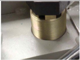
- At least one full round of thread must be visible above the lock ring at all adjuster locations.note:
The table may not have lock rings; nevertheless, one full round of thread must be showing above the base (see Figure 3).
Figure 3. Table Base With No Lock Ring