- Topic ID: id_15460691
- Version: 3.0
- Date: Jun 15, 2020 11:00:20 PM
Accessories Replacement
Prerequisites
Overview
This procedure describes and illustrates the steps necessary to replace the Keyboard, Mouse, Trackball or Barcode Reader. Since the processes for replacing these parts are so similar, the Keyboard, Mouse, Trackball and Barcode Reader replacement instructions have been combined in this procedure. For all replacement parts see the parts list located in the Parts folder of this service methods publication.
1 Power-Off (Shut Down) the Console
Procedure
- Select one of the following methods to power off the Operator
Console:
-
If applications are running, click the Shut Down icon and select Shut Down.
-
If applications are down, open a Unix Shell using the Toolchest. Type: {ctuser@hostname} halt. Press Enter.
The Operator Console monitor will display a ‘System Halted’ message when it is acceptable to power off the Operator Console.
-
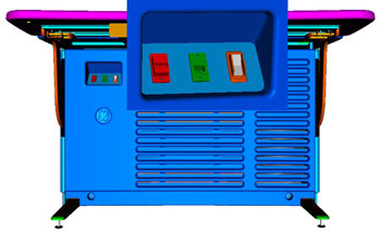
- Power OFF the Operator Console at the front panel switch. (See
Illustration 2.)
Figure 1. Console Power Switch
- Perform prescribed Lockout/Tagout procedure. For added protection, disconnect the Twist-N-Lock Main Power Cable from rear of console.
2 Remove the Old Keyboard, Mouse, Trackball or Barcode Reader
Procedure
- Remove the USB cable connection from the Console’s Upper Bulkhead Panel for the Keyboard, Mouse, Trackball or Barcode Reader being replaced.
- Remove the Keyboard, Mouse, Trackball or Barcode Reader and set aside.
3 Install the Replacement Keyboard, Mouse, Trackball or Barcode Reader
Procedure
- Place the replacement Keyboard, Mouse, or Trackball on the Operator Console.
- Plug in Keyboard, Mouse, Trackball or Barcode Reader cable in
the USB connector at the Rear Bulkhead Panel. Refer to Illustration
2 to confirm correct connections.
Figure 2. Upper Bulkhead Panel Connections
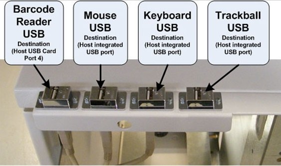 note: Console design requires specific USB locations (Figure 2) for proper operation.
4 GOC6 Console Equipped with PS/2 Type Keyboards and/or Mouse
Procedure
- Remove Rear Console Cover to allow access to the Host Computer.
- Disconnect either the Keyboard or Mouse from its respective PS/2 Port on the rear of the Host Computer.
- Connect the replacement Keyboard or Mouse.
Note: Green PS/2 Port is for Mouse, Purple PS/2 Port is for Keyboard.
- Pass the PS2 keyboard or Mouse cable along the underside of the Upper Rear Bulkhead panel at the top of the console cabinet, along with the Monitor Video and DVD Peripheral Tower USB cables. Affix a tie wrap to secure the Keyboard or Mouse cable to the Upper Rear Bulkhead Panel.
- Re-install Rear Console Cover.
5 Power-On the Operator Console
Procedure
- Power ON the Operator Console at the console front panel switch.
6 Verify Replacement Keyboard, Mouse, Trackball or Barcode Reader Operation
Procedure
- Visually verify Keyboard, Mouse, Trackball or Barcode Reader works as expected with the CT Applications.
- No other verifications required.note: This procedure assumes that like type Keyboard, Mouse, Trackball or Barcode Reader has been used in the replacement process. If Keyboard language type or different style Mouse or Trackball are used, there may be Operating Software and/or System Configuration issues. Use GE Healthcare recommended spare parts.note: Keyboard and Mouse functionality is readily apparent and easy to verify proper operation. Trackball functionality is not so readily apparent since functions vary based on Application usage. Refer to the system's Technical Reference Guide for Trackball functionality description.
7 Finalization
No finalization steps.