- Topic ID: id_15460495
- Version: 2.0
- Date: Nov 8, 2018 1:37:30 AM
VeRB Troubleshooting
[Introductory material]
1 OVERVIEW
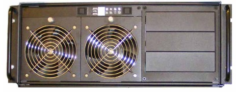
The follow information will assist in confirming if the VeRB Computer is experiencing a hardware fault. Although the following is not a complete set of diagnostics, it should be sufficient in determining if the VeRB Computer is suffering from hardware issues at the prescribe Field Replaceable Unit (FRU) level.
Figure 1. VeRB Computer
|

TO PREVENT DAMAGE TO COMPONENTS WITHIN THE HSDA, OBSERVE THE FOLLOWING ESD PRECAUTIONS:
-
WORK ON A STATIC-FREE MAT.
-
WEAR A STATIC STRAP TO ENSURE THAT ANY ACCUMULATED ELECTROSTATIC CHARGE IS DISCHARGED FROM YOUR BODY TO GROUND.
-
CREATE A COMMON GROUND FOR THE EQUIPMENT YOU ARE WORKING ON BY CONNECTING THE STATIC-FREE MAT, STATIC STRAP AND PERIPHERAL UNITS TO THAT PIECE OF EQUIPMENT.
FOR FURTHER INFORMATION REGARDING ESD PROTECTION, REFER TO THE SAFETY CHAPTER IN THIS PUBLICATION
2 VeRB COMPUTER GENERAL TROUBLESHOOTING
Before proceeding with the rest of this guide, use the following checklists to find possible solutions for VeRB Computer problems.
2.1 Power Checklist
-
Is the VeRB Computer powered on?
-
Is the front panel green power light illuminated on VeRB?
-
Has Circuit Breakers #1 or #2 (CB1 or CB2) tripped on Power Distribution Box?
-
Is the VeRB Computer connected to a working electrical outlet on the Power Distribution Box?
-
Has the VeRB PSU Switch been turned on (on back of VeRB chassis)?
2.2 Cable Checklist
Examine all cables for:
-
Loose connections
-
Incorrect connections
3 VeRB Remote Management Module (RMM)
The VeRB computer is equipped with a Remote Management Module (RMM), with its own dedicated Ethernet network access. The RMM is a self contained micro computer running operating and application software embedded within the firmware of the RMM card. As long as the standby power (3.3V) of the VeRB computer’s power supply is present, the RMM will operate and allow access from the Host Computer.
The RMM in the VeRB Computer provides the means for virtual presence (remote console) at the Host Computer. This presence includes keyboard, video and mouse redirection. By utilizing a RMM in the DIG Computer, an independent path for communication and hardware status checking can be established without the need of a fully functioning VeRB Computer.
The RMM functionality replaces the Serial over LAN (SOL) functionality used in previous console generations.
 |
|
3.1 RMM Access
-
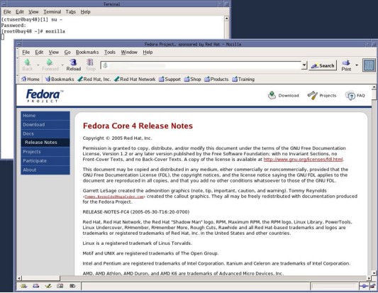
To access the RMM, open a Terminal Window, and log on as root:
Type: {ctuser@hostname}su – and press ENTER
Type the root password and press ENTER
-
Launch the Mozilla WEB Brower:
Type: [root@hostname]mozilla and press ENTER
The Mozilla (Fedora) WEB Browser (Figure 2) will appear.
Figure 2. Mozilla WEB Browser
-
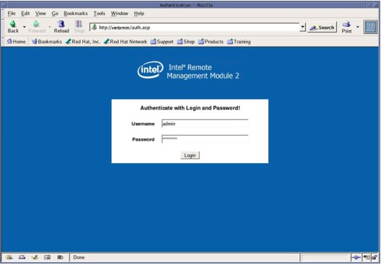
In the WEB Browser URL Address Bar:
Type: verbrmm and press ENTER
-
The WEB Browser will update and display the Login page (Figure 3) for the VeRB RMM.
Username: Type: admin and press TAB
Password Type: password and press ENTER
Figure 3. VeRB RMM Login Page
-
The WEB Browser will update and display the Home page (Figure 4) for the VeRB RMM.
Figure 4. VeRB RMM Home Page
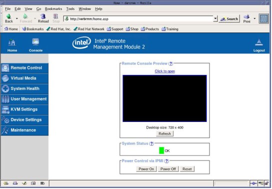
3.2 VeRB Computer RMM Navigation
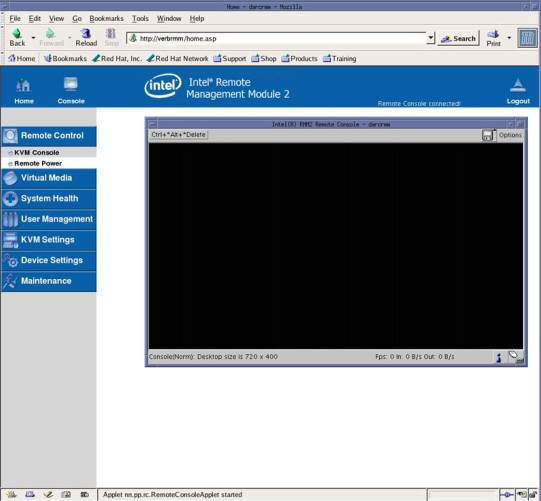
By clicking on Console, the Remote Console Preview window, or Remote Control/KVM Console, a new window will open displaying the VeRB Computer’s display. In other words the VeRB Computer’s video will be redirected to the Host Computer’s display and displayed in the WEB Browser’s Remote Console window (Figure 5). This feature will allow the user to view the following:
-
VeRB Video Display – In normal operating mode
-
VeRB Bootup – When VeRB is reset independently
-
VeRB BIOS Settings – When F2 is pressed at start of VeRB bootup
Figure 5. VeRB RMM Remote Console
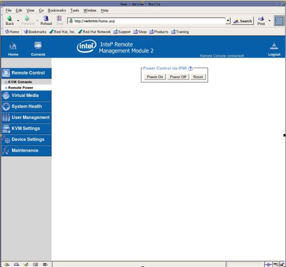
By clicking on Remote Control/Remote Power, the VeRB Computer can be reset or power can be turned ON and OFF.
note:Resetting the VeRB Computer or toggling power takes a few minutes to process.
Figure 6. VeRB RMM Remote Control / Remote Power
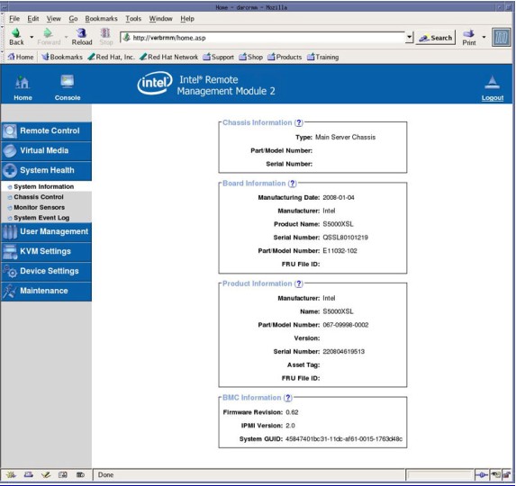
By clicking on System Health, you can check the VeRB Computer’s hardware revisions. System Board information will be displayed.
Figure 7. VeRB RMM System Health
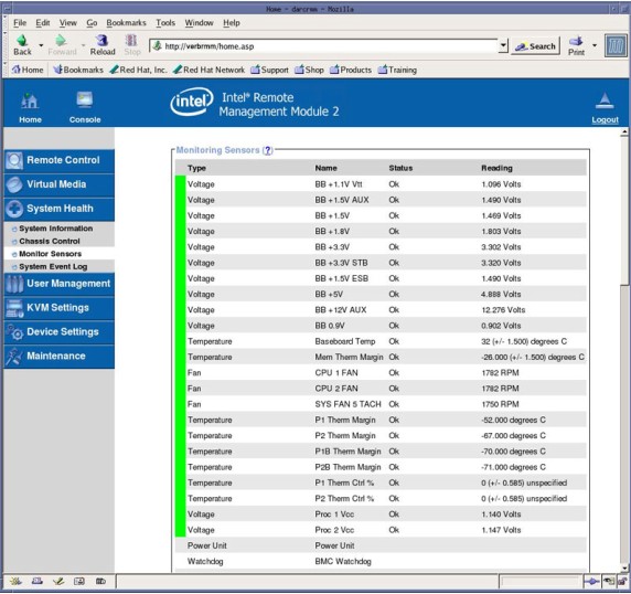
By clicking on System Health / Monitor Sensors, you can monitor the VeRB Computer’s IPMI sensors. This is useful for determining if hardware failures are present or operating temperatures are being exceeded.
Figure 8. VeRB RMM System Health / Monitor Sensors
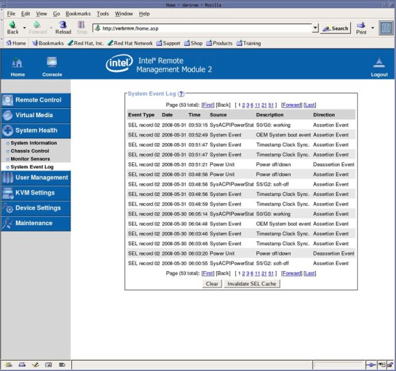
By clicking on System Health / System Event Log, you can view the VeRB Computer’s RMM event logging. This is useful for determining if hardware failures are present.
Figure 9. VeRB RMM System Health / System Event Log
4 VeRB Computer Troubleshooting – LEDS
The VeRB Computer has numerous status LEDs mounted on the motherboard and chassis that can indicate hardware faults and operational status of the computer. Some of these LEDs are visible on either the front or back of the VeRB Computer chassis while others require that the VeRB Computer be removed from the console, AC power applied and chassis cover removed.
4.1 External Status LEDs
4.1.1 VeRB Computer Chassis Front Panel Indicators
Figure 10. VeRB Front Panel Indicators
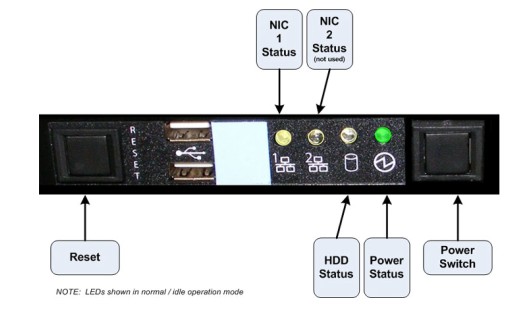
The Power Status LED has the following states:
-
Power Status LED has no color showing: PC is off or is in Sleep Mode (not used).
-
Solid Green: Host PC on.
The NIC LEDs have the following states:
-
NIC LED has no color showing: No connection.
-
Solid Amber: NIC is linked.
-
Blinking Amber: NIC Activity
The HDD Status LED has the following states:
-
HDD Status LED has no color showing: No HDD Activity.
-
Blinking Amber: HDD Activity.
4.1.2 VeRB Computer Chassis Rear Panel Indicators
Figure 11. System Status, ID, POST and NIC LED Locations
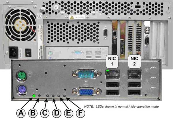
System Status LED (A)
System ID LED (B)
System Post LEDs (C - F)
During VeRB Computer boot process, the BIOS executes a number of platform configuration processes, each assigned a specific hex POST code number. As each configuration routine is started, the BIOS will display the given POST code to the POST LEDs. To assist in troubleshooting a system hang during POST process, the POST LEDs can be used to identify the last POST process to be executed and the corresponding fault indications.
NIC Status LEDs
4.2 Internal Status LEDs
|
|
|
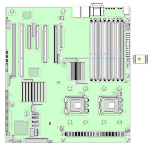
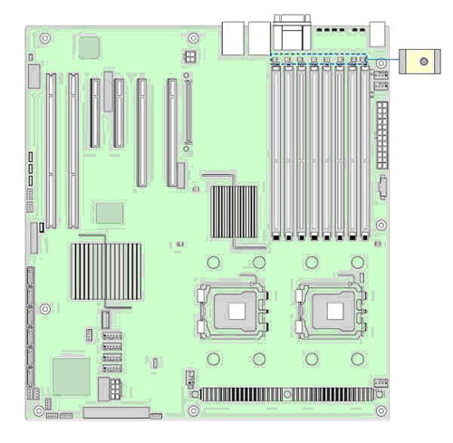
4.2.1 5 Volt Standby LED (motherboard)
The VeRB Computer motherboard has a LED mounted towards the middle of the board that indicated that the Power Supply is under power and is supplying 5 Volt Standby power to the VeRB computer. As long as the VeRB computer is plugged into an energized AC Power source, this LED should be operational. If LED is not illuminated, suspect either a faulty PSU or motherboard in the VeRB Computer.
Figure 12. 5 Volt Standby Status LED Location
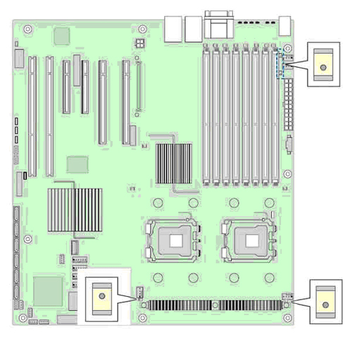
4.2.2 Fan Fault LEDs (motherboard)
The VeRB Computer motherboard has two (2) CPU Fan LEDs mounted close to the CPU Fan headers and two (2) System Chassis Fan LEDs mounted close to the rear of the motherboard, which indicated that the Fans are faulty in the VeRB computer.
Figure 13. Fan Fault Status LED Location
4.2.3 Memory DIMM Fault LEDs (motherboard)
The VeRB Computer motherboard has Memory DIMM fault indicator LED associated with each DIMM Socket location. If LED is illuminated, suspect a bad memory module.
Figure 14. Memory DIMM Fault LEDs Location
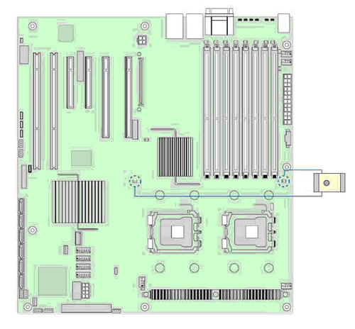
4.2.4 CPU Fault LEDs (motherboard)
The VeRB Computer motherboard has CPU fault indicator LED associated with each CPUs. If LED is illuminated, suspect a bad processor.
Figure 15. CPU Fault LEDs Location
5 VeRB COMPUTER POST CODE ERRORS (VIDEO SCREEN)
Whenever possible the VeRB Computer BIOS will output current boot progress codes on a video screen. The codes may be reported by the system BIOS or option ROMs.
The response column in the following table is divided into two (2) types:
-
Pause: The message is displayed in the Error Manager screen, an error is logged to the System Event Log (SEL), and use input is required to continue. The user can take immediate corrective action or choose to continue.
-
Halt: The message is displayed in the Error Manager screen, an error is logged to the SEL, and the system cannot boot unless the error is resolved.