- Topic ID: id_15460659
- Version: 3.0
- Date: Sep 30, 2019 9:26:00 PM
HSDA Troubleshooting
1 Overview
The following information will assist in confirming if the HSDA is experiencing a hardware fault. Although the following is not a complete set of diagnostics, it should be sufficient in determining if the HSDA is suffering from hardware issues at the prescribe Field Replaceable Unit (FRU) level.
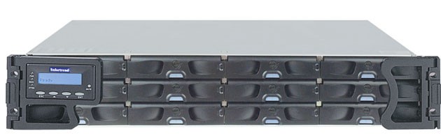
Figure 1. High Speed Disk Array (HSDA)
|

2 HSDA General Troubleshooting
Before proceeding with the rest of this guide, use the following checklist to find possible solutions for HSDA problems.
-
Is the HSDA powered on?
-
Is the HSDA connected to the proper electrical outlet on the Power Distribution Box?
-
Has Circuit Breaker #1 or #2 (CB1 or CB2) tripped on Power Distribution Box?
-
Are the AC Power Cords fully seated in the PSU Modules?
-
Are the rear panel PSU Power LEDs illuminated Green?
note:The HSDA has two (2) redundant PSU Modules. The HSDA will continue to work with only one functioning PSU. A failed PSU Module should be replaced as soon as possible to prevent a complete failure of the HSDA in the event the second PSU Module should malfunction.
-
-
Examine all cables for loose or incorrect connections.
-
Network Cable
-
SAS Controller Cable
-
3 HSDA Troubleshooting - WEB Browser (Mozilla)
The HSDA is equipped with Java (WEB) interface functionality via the RAID Controller Module and its dedicated Ethernet network access. By utilizing this functionality in the HSDA, an independent path for communication and hardware status checking can be established without the need of a fully functioning HSDA.
The Java (WEB) functionality of the RAID Controller Module in the HSDA provides the means for virtual presence (remote console) at the Host Computer. This presence includes keyboard, video and mouse redirection. As long as the standby power of the HSDA power supply is present, the RAID Controller Module will operate and allow access from the Host Computer.
 |
|
3.1 WEB Browser Access
-
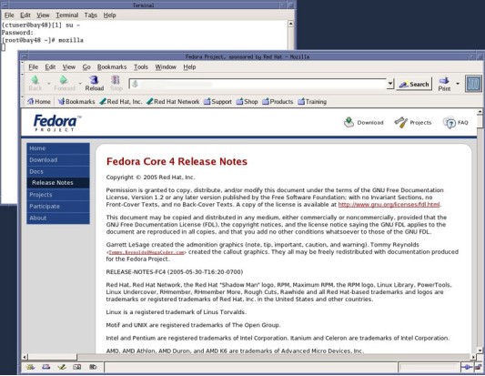
To access the HSDA, open a Terminal Window, and log on as root:
Type: {ctuser@hostname}su – and press ENTER
Type the root password and press ENTER
-
Launch the Mozilla WEB Brower:
Type: [root@hostname]mozilla and press ENTER
The Mozilla (Fedora) WEB Browser (HSDA WEB Browser Navigation) will appear.
Figure 2. Mozilla WEB Browser
-
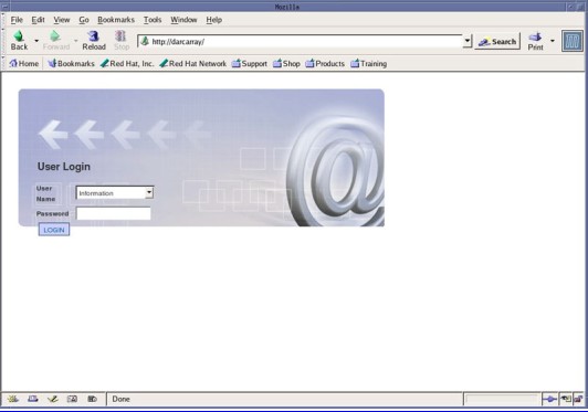
In the WEB Browser URL Address Bar:
Type: darcarray and press ENTER
note:Type: darcarray2 for second HSDA (for CT750HD Only).
-
The WEB Browser will update and display the Login page (Figure 3) for the HSDA.
Username: Type: Information and press TAB
Password Type: ( blank ) and press ENTER
Figure 3. HSDA Login Page
-
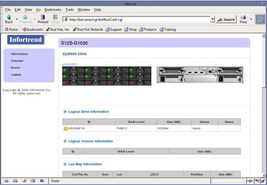
The WEB Browser will update and display the HSDA Home / Information Page (Figure 4) for the HSDA.
Figure 4. HSDA Home / Information Page
3.2 HSDA WEB Browser Navigation
At the HSDA Home page (defaults to Information page), or by clicking on Information, a visual display of hardware status will be shown in real time (Figure 4). This allows the user to view the following:
-
HSDA Individual HDD Status - Green (OK) Red (HDD Failure or Not Present)
-
HSDA Raid Controller Module Status - Green (OK) Red (Failed or Off Line)
-
HSDA PSU Module Status - Green (OK) Red (Failed)
-
HSDA Cooling Module Status - Green (OK) Red (Failed)
In addition, key hardware information will be listed including:
-
Controller Module and Firmware Revisions
-
Temperature Sensors
-
Power Supply Voltages
-
Fan Status
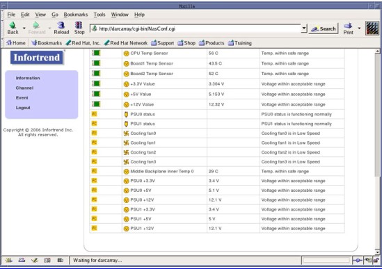
Figure 5. HSDA Information Page 1
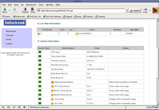
Figure 6. HSDA Information Page 2
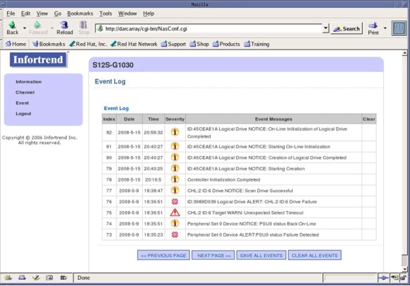
By clicking Event, the HSDA Event Log (Figure 7) can be viewed.
Figure 7. HSDA Event Page
4 HSDA Troubleshooting – LEDs
The HSDA has numerous status LEDs mounted on the chassis that can indicate hardware faults and operational status of the array. These LEDs are visible on either the front or back of the HSDA.
4.1 Status LEDs (Front)
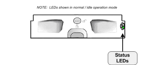
4.1.1 HSDA Keypad/LCD Panel Indicators
Figure 8. Front Keypad/LCD Panel Indicators
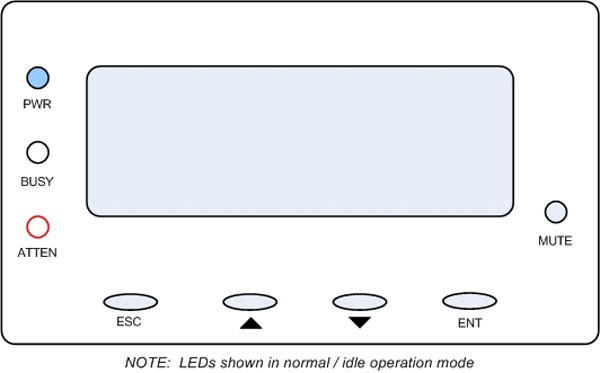
During Power On process, the ATTEN LED will light up steadily. Once the HSDA successfully boots up with no faults, the ATTEN LED is turned off.
4.1.2 HSDA Drive Tray Indicators
Figure 9. HDD Tray Indicators
LED indicators are located on the right side of each of the HDD trays. When notified by a drive failure message, one should check the drive tray indicators to find the correct location of the failed drive. Replacing the incorrect drive can fatally fail a logical drive array.
4.2 Status LEDs (Rear)
4.2.1 HSDA Controller Module Indicators
Figure 10. HSDA Controller Module Indicators
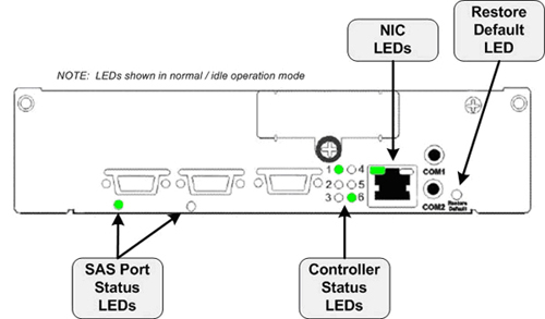
“PHY” is a term used with Serial Attached SCSI (SAS) interfaces to describe the lower physical layers of the SAS Protocol.
* The Battery Backup Unit (BBU) is not utilized in the HSDA.
Restore Default LED
A Restore Default LED is located above the Restore Default push button on the lower right corner of the HSDA Controller Module. To restore firmware defaults, press and hold the button down before turning on the HSDA. Once the factory defaults are successfully restored, release the button after the Restore Default LED lights green.
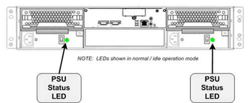
4.2.2 HSDA PSU Module Indicators
Figure 11. HSDA PSU Module Indicators
4.2.3 HSDA Fan Cooling Module Indicators
Figure 12. HSDA Cooling Module Indicators
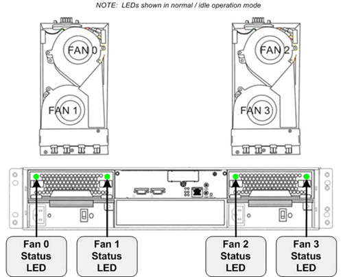
When temperature sensors detect an elevated temperature reading or the failure of any cooling fan, firmware in the HSDA will instruct the remaining cooling fans to operate at a high speed. Once the temperature falls back within the safe range or the fault condition is corrected, cooling fans will resume the low speed.
5 HSDA Command Mode Troubleshooting
The following describes the Command Mode method for troubleshooting the HSDA. By using a Terminal Window on the Host Computer and the operator console's network interface, HSDA hardware and event status can be obtained.
5.1 Java “raidcmd2” Tool
5.1.1 Tool Access
-
To access the HSDA from the Host Computer, open a Terminal Window, and log on as root:
Type: {ctuser@hostname}su – and press ENTER
Type the root password and press ENTER
-
Launch the Java “raidcmd2” Tool:
Type: [root@hostname]java -jar /usr/g/scripts/raidcmd2.jar and press ENTER
-
Then connect to the HSDA hostname you want to look at:
Type: connect darcarray and press ENTER
5.1.2 Commands
5.1.3 Command Details and Result Examples
Command show disk
Example of show disk command output:
[root@rsna1 ~]# java -jar /usr/g/scripts/raidcmd2.jar
RAIDCmd:> connect darcarray
Primary Agent Version 4.0@
1: Device(UID:233913)
device Device(UID:233913, Name:, Model:S12S-G1030) selected.
RAIDCmd:> show disk
index Slot ID Size Speed LG_DRV Status Vendor Serial
------------------------------------------------------------------------------------------------------
0 1 0 238470 300MB 54F19433 On-Line ST3250310NS 9SF04D7R
1 2 1 238470 300MB 54F19433 On-Line ST3250310NS 9SF05EKZ
2 3 2 238470 300MB 54F19433 On-Line ST3250310NS 9SF04CW3
3 4 3 238470 300MB 54F19433 On-Line ST3250310NS 9SF05AHX
4 5 4 238470 300MB 54F19433 On-Line ST3250310NS 9SF05E7J
5 6 5 238470 300MB 54F19433 On-Line ST3250310NS 9SF0563G
6 7 6 238470 300MB 54F19433 On-Line ST3250310NS 9SF05JS3
7 8 7 238470 300MB 54F19433 On-Line ST3250310NS 9SF05KNM
8 9 8 Absent
9 10 9 Absent
10 11 10 Absent
11 12 11 Absent
------------------------------------------------------------------------------------------------------
Total: 12
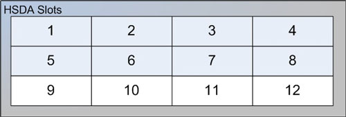
Command show disk Slot Definitions:
Figure 13. Slot Definition to Physical Location on HSDA
Command show disk Status Definitions:
-
On-Line
Hard Disk Drive is functioning and included in Logical Disk of array.
-
Used
Hard Disk Drive is no longer included in Logical Disk, but is detected. This may be due a drive failure, read/write errors, or a new drive added since the last logical disk creation and reboot. Requires service attention!
-
Absent
Hard Disk Drive is not physically present or failure to detect the presence of drive.
Command show ld
Example of show ld Command Output:
RAIDCmd:> show ld
ID RAID Size Stripe Max Size Status LV
---------------------------------------------------------------------------
P[0] 54F19433 RAID5 523264 128KB 1667498 Good
[Member Disk]---------------------------------------------------------------------------------
Slot ID Size Speed LG_DRV Status Vendor
----------------------------------------------------------------------------------------------
1 0 238214 300MB 54F19433 On-Line ST3250310NS
2 1 238214 300MB 54F19433 On-Line ST3250310NS
3 2 238214 300MB 54F19433 On-Line ST3250310NS
4 3 238214 300MB 54F19433 On-Line ST3250310NS
5 4 238214 300MB 54F19433 On-Line ST3250310NS
6 5 238214 300MB 54F19433 On-Line ST3250310NS
7 6 238214 300MB 54F19433 On-Line ST3250310NS
8 7 238214 300MB 54F19433 On-Line ST3250310NS
----------------------------------------------------------------------------------------------
Total: 8
Command show map
Example of show map Command Output:
RAIDCmd:> show map
[Ch:0][ID:0][Lun:0] type:LD ID:54F19433 P0 RAID:RAID5 Size(MB):523264 Status:Good
Command show map Status Definitions
-
Good
Disk Array is functioning and all Hard Disk Drives are included in Logical Disk.
-
Degraded
Disk Array is functioning, but at least one Hard Disk Drive is no longer included in Logical Disk. Requires service attention!
Command show event
Example of show event Command Output:
Event Log is maintained on the RAID Controller of HSDA.
RAIDCmd:> show map
[Ch:0][ID:0][Lun:0] type:LD ID:54F19433 P0 RAID:RAID5 Size(MB):523264 Status:Good
RAIDCmd:> show event
<1, 2008/07/10 16:19:33>: NOTICE:NVRAM Factory Defaults Restored
<2, 2008/07/10 16:20:47>: Controller Initialization Completed
<3, 2008/07/10 16:24:33>: ID:61C5928 Logical Drive NOTICE: Starting Creation
<4, 2008/07/10 16:24:38>: ID:61C5928 Logical Drive NOTICE: Creation of Logical Drive Completed
<5, 2008/07/10 16:24:38>: ID:61C5928 Logical Drive NOTICE: Starting On-Line Initialization
<6, 2008/07/10 10:41:31>: ID:61C5928 Logical Drive NOTICE: On-Line Initialization of Logical Drive Completed
<7, 2008/07/10 14:09:44>: Controller Initialization Completed
<8, 2008/07/24 10:31:23>: Controller Initialization Completed
<9, 2008/07/24 10:48:09>: Controller Initialization Completed
<10, 2008/07/24 10:59:07>: Controller Initialization Completed
<11, 2008/07/24 11:17:11>: Controller Initialization Completed
<12, 2008/07/24 11:27:41>: Controller Initialization Completed
<13, 2008/07/24 12:22:02>: Controller Initialization Completed
<14, 2008/10/02 19:05:18>: LG:0 Logical Drive ALERT: Incomplete Array
<15, 2008/10/02 19:05:18>: Controller Initialization Completed
<16, 2008/10/08 17:03:33>: LG:0 Logical Drive ALERT: Incomplete Array
<17, 2008/10/08 17:03:33>: Controller Initialization Completed
<18, 2008/10/09 08:18:18>: LG:0 Logical Drive ALERT: Incomplete Array
<19, 2008/10/09 08:18:18>: Controller Initialization Completed
<20, 2008/10/09 08:30:10>: LG:0 Logical Drive ALERT: Incomplete Array
<21, 2008/10/09 08:30:10>: Controller Initialization Completed
<22, 2008/10/09 08:34:55>: ID:54F19433 Logical Drive NOTICE: Starting Creation
<23, 2008/10/09 08:34:56>: ID:54F19433 Logical Drive NOTICE: Creation of Logical Drive Completed
<24, 2008/10/09 08:34:57>: ID:54F19433 Logical Drive NOTICE: Starting On-Line Initialization
<25, 2008/10/09 08:52:03>: ID:54F19433 Logical Drive NOTICE: On-Line Initialization of Logical Drive Completed
<26, 2008/10/09 09:05:09>: Controller Initialization Completed
<27, 2008/10/09 11:34:44>: Controller Initialization Completed
<28, 2008/10/10 20:27:37>: Controller Initialization Completed
<29, 2008/10/13 00:22:36>: Controller Initialization Completed
<30, 2008/10/13 05:01:43>: Controller Initialization Completed
<31, 2008/10/13 05:07:10>: Controller Initialization Completed
<32, 2008/10/13 05:29:36>: Controller Initialization Completed
<33, 2008/10/13 19:23:29>: Controller Initialization Completed
<34, 2008/10/13 19:37:14>: Controller Initialization Completed
<35, 2008/10/23 14:24:59>: Controller Initialization Completed
<36, 2008/10/28 13:32:18>: Controller Initialization Completed
Command show enclosure
Example of show enclosure Command Output:
RAIDCmd:> show enclosure
-------------------------------------------------------------------------------------------------------------
Vendor id- HwVer- SwVer- LUId-S12S-G1030 Type-CUSTOMABLE_I2C_PERIPHERAL_DEVICE
-------------------------------------------------------------------------------------------------------------
ObjId Device attribute capability UnitType Type Index Vendor value status
-------------------------------------------------------------------------------------------------------------
7 PSU0 status 0 1 POWER_SUPPLY PSU0 status 1 PSU0 status functioning normally
8 PSU1 status 0 1 POWER_SUPPLY PSU1 status 2 PSU1 status functioning normally
15 Cooling fan0 0 1 FAN Cooling fan0 1 Cooling fan0 is in low speed
16 Cooling fan1 0 1 FAN Cooling fan1 2 Cooling fan1 is in low speed
17 Cooling fan2 0 1 FAN Cooling fan2 3 Cooling fan2 is in low speed
18 Cooling fan3 0 1 FAN Cooling fan3 4 Cooling fan3 is in low speed
19 Middle Backplane Inner 0 1 TEMPERATURE_SENSOR Middle Backplane Inner Temp 0 1 24.0 C Temp. within safe range
9 PSU0 +3.3V 0 1 VOLTAGE_SENSOR PSU0 +3.3V 3 3.4V Voltage within acceptable range
10 PSU0 +5V 0 1 VOLTAGE_SENSOR PSU0 +5V 4 5.0V Voltage within acceptable range
11 PSU0 +12V 0 1 VOLTAGE_SENSOR PSU0 +12V 5 12.1V Voltage within acceptable range
12 PSU1 +3.3V 0 1 VOLTAGE_SENSOR PSU1 +3.3V 6 3.4V Voltage within acceptable range
13 PSU1 +5V 0 1 VOLTAGE_SENSOR PSU1 +5V 7 5.1V Voltage within acceptable range
14 PSU1 +12V 0 1 VOLTAGE_SENSOR PSU1 +12V 8 12.3V Voltage within acceptable range
--------------------------------------------------------------------------------------------------------------
Total: 13
--------------------------------------------------------------------------------------------------------------
Vendor id- HwVer- SwVer- LUId- Type-CONTROLLER_PERIPHERAL_DEVICE
--------------------------------------------------------------------------------------------------------------
ObjId Device attribute capability UnitType Type Index Vendor value status
--------------------------------------------------------------------------------------------------------------
3 CPU Temp Sensor 0 1 TEMPERATURE_SENSOR CPU Temp Sensor 1 54.0 C Temp. within safe range
4 Board1 Temp Sensor 0 1 TEMPERATURE_SENSOR Board1 Temp Sensor 2 39.0 C Temp. within safe range
5 Board2 Temp Sensor 0 1 TEMPERATURE_SENSOR Board2 Temp Sensor 3 49.0 C Temp. within safe range
0 +3.3V Value 0 1 VOLTAGE_SENSOR +3.3V Value 1 3.32 V Voltage within acceptable range
1 +5V Value 0 1 VOLTAGE_SENSOR +5V Value 2 5.153 V Voltage within acceptable range
2 +12V Value 0 1 VOLTAGE_SENSOR +12V Value 3 12.32 V Voltage within acceptable range
--------------------------------------------------------------------------------------------------------------
Total: 7
5.2 HSDA and System Configuration (“reconfig”) Utility
In the event that HSDA is shown to be “degraded” (show map command) or an individual disk drive is shown as “used” (show disk or show ld commands), service attention is needed. In these conditions, one of the disk drives is no longer included in the logical disk array. The RAID 5 aspect (redundancy) of the array is no longer applicable and risk of losing scan data is increased. In the event a second disk drive failure, they entire HSDA will fail.
In the event a disk drive is listed as “used”, replace the disk drive. Follow the instructions for replacing a Disk Drive found in HSDA HDD Replacement Procedure
In the HSDA HDD Replacement Procedure, the System Configuration (“reconfig”) Utility is used for repairing the logical disk array.
System Configuration (“reconfig”), System Tab Options
-
Regenerate Scan Database
Destructive! Creates new Scan Database on the HSDA/s. Use only if Scan Data corruption is suspected and HSDA hardware appears to be operational. All Scan Data presently on HSDA will be lost. (In case of the CT750HD system this includes both HSDAs.)
-
Recreate Scan Disk Array
Destructive! Creates new Logical Disk on HSDA/s. Use only if replacing multiple disk drives or replacement of entire HSDA. All data will be lost. (In case of the CT750HD system this includes both HSDAs.)
-
Rebuild Scan Disk Array
Non-Destructive. Used for including one new disk drive in the array. The logical disk is rebuilt to include new disk drive by using the redundancy aspect of the RAID 5 feature of the HSDA. Will take approximately 20 minutes to perform. This Option only appears on the System Tab when a degraded array is detected.